Keyed Shaft Coupling Position Checklist
Reference Standard: Relevant material and performance testing standards for mechanical hardware inspection may include dimensional verification practice, visual finish review, and general fastener fit assessment. For broader reference, buyers can compare supplier inspection language with resources from ASTM Internacional y ISO, while keeping the catalog-confirmed shaft coupling data separate from any unverified performance claim.
Short Answer
Keyed Shaft Coupling Position Memory Checklist
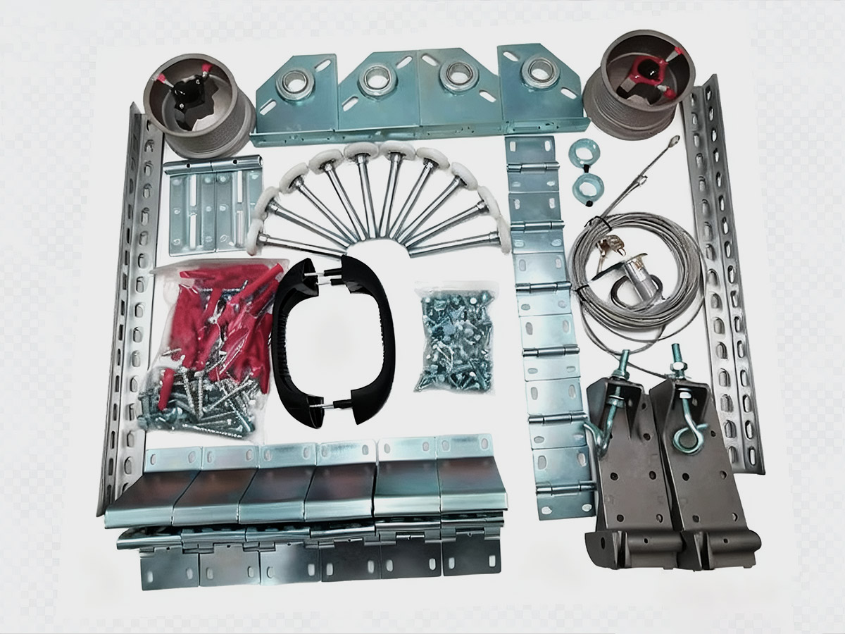
A acoplamiento de ejes con chaveta used in garage door shaft transmission has a simple catalog identity, but its field value is more subtle. The confirmed product data includes BT-SH604 Shaft Key with 6.356.3575 mm size for shaft use, BT-SH605 with 1 inch inside diameter, 90mm length, y aluminum material, BT-SH606 with 1 inch inside diameter, 90mm length, y galvanized finish, BT-SH607 with 1 inch inside diameter, 120mm length, y aluminum material, BT-SH608 with 1 inch and 1-1/4 inch inside diameter y galvanized finish, BT-SH609 with 1 inch inside diameter, 120mm length, y galvanized finish, BT-SH610 with 1-1/4 inch inside diameter, 120mm length, y galvanized finish. These values create the factual boundary of the article. No material grade, hardness value, torque rating, coating thickness, salt-spray duration, or tensile rating is confirmed in the supplied catalog data.
The useful angle is not simple connection. A coupler becomes a position memory component after the installer leaves the job site. The bore diameter, coupler length, shaft key, and visible finish together decide whether the shaft remains where the repair intended it to remain. The 90 mm body gives one style of overlap control, while the 120 mm body gives a longer contact envelope. That does not automatically mean one is stronger in every application, because actual performance also depends on shaft condition, keyway condition, set-screw condition, alignment, and service load. The safe procurement position is more modest: the buyer should treat length and bore data as the first verified filter, then request drawings, tolerance notes, or sample confirmation before making any load claim.
An edge extreme scenario helps explain the risk. Imagine a garage door shaft assembly where one side is replaced during maintenance and the shaft end is slightly polished from prior use. A 1 inch inside diameter coupler can still appear visually correct, but the holding result depends on how consistently the internal bore contacts the shaft and how the key limits relative rotation. During the initial service period, the assembly may appear calm. In the middle period, small rotational movement can polish contact points. In the extreme period, the coupler may still be present on the shaft, yet the original installed reference position may no longer be trustworthy. This is not a catalog defect claim; it is a mechanical reality of contact pressure, surface friction, and positional memory.
A cross-dimensional comparison test can be built without inventing lab data. Compare two inspection paths. Path A checks only whether a 1 pulgada o 1-1/4 inch shaft enters the coupler. Path B checks bore match, length match, shaft key match, visible finish, and post-service position mark. Path B is more useful because it separates static assembly from retained alignment. The key lesson is that a coupling is not fully evaluated at the moment it slides into place. It should also be evaluated as a part that must remember its placement after vibration, door cycles, humidity exposure, and maintenance handling have had time to influence the assembly.
The Hidden Boundary Between Key Contact and Coupler Body Support
A keyed assembly divides work between two physical zones. The BT-SH604 Shaft Key, sized 6.356.3575 mm, supports directional positioning at the keyway relationship. The shaft coupler body supports surrounding contact and shaft overlap. Treating these as the same function creates poor inspection language. The key is not a full-body clamp. The coupler body is not a substitute for correct key engagement. A practical checklist must ask whether both zones are doing their own job without forcing one component to compensate for the other.
The mechanical mechanism is based on contact geometry. A shaft key provides a defined interface that resists relative angular movement between the shaft and the coupled element. The coupler body provides a cylindrical contact environment where bore diameter, length, finish, and fastener behavior influence how the assembly stays aligned. With 90 mm y 120 mm coupler lengths in the catalog-confirmed range, the contact envelope is visible as a procurement variable, but the exact load capacity remains unconfirmed. The buyer should not translate a longer coupler into a guaranteed strength figure. The more accurate statement is that a longer body changes the available support region and may help distribute contact over a longer installed area when the rest of the assembly is appropriate.
An edge extreme scenario can be imagined around key-function drift. Suppose the 6.356.3575 mm shaft key is present, and the coupler bore is nominally correct, but the shaft key slot in the customer’s existing shaft has wear. The coupler may still look centered, yet the key may carry directional movement unevenly. At the early stage, the issue may show as minor witness marks. At the middle stage, rotational play may become easier to feel during service inspection. At the extreme stage, the coupler body may remain visually acceptable while the key interface becomes the weak interpretive point. The root cause is not one single catalog dimension. It is the relationship between key geometry, shaft condition, bore support, and contact pressure.
| Inspection Question | Confirmed Catalog Anchor | What It Can Support | What It Cannot Prove Alone |
|---|---|---|---|
| Is the shaft key identified? | BT-SH604, 6.356.3575 mm | Key size recognition | Full keyway tolerance |
| Is the bore family selected? | 1 inch, 1-1/4 inch, or mixed bore | Shaft matching direction | Actual installed clearance |
| Is the body length selected? | 90mm or 120mm | Overlap planning | Load rating |
| Is the surface route visible? | Aluminum or galvanized | Exposure planning | Coating thickness |
| Is the assembly stable after use? | Requires field review | Maintenance confidence | Factory-certified life |
A cross-system comparison is useful here. In a purely round sleeve without a shaft key, the body contact and fastener pressure must manage more of the rotational relationship. In a keyed shaft coupling, the key creates a separate reference feature. That split can be valuable, but only if the key and body are both controlled. This is why a buyer should request item-level confirmation, not only a general hardware quotation. The safest communication is: confirm bore, length, finish, key size, and compatibility with the actual shaft type.
KEY TAKEAWAYS
- A coupler that still looks centered may still need key-interface review after service use.
- A 90 mm o 120 mm length confirms body size, not an automatic load rating.
- En 6.356.3575 mm shaft key should be checked as a directional reference part, not as loose small hardware.
Aluminum and Galvanized Couplers Under Service-Area Exposure
The catalog confirms two surface or material routes for the shaft coupler family: aluminum on selected models and galvanized finish on selected models. This is enough to build a service-area exposure checklist, but not enough to claim a specific alloy grade, zinc thickness, salt-spray result, or corrosion warranty. A careful article must keep that boundary visible. Aluminum and galvanized surfaces behave differently in garage door and industrial door environments because moisture, dust, hand contact, adjacent steel parts, and maintenance residue can all affect visible condition.
Aluminum is commonly valued where lower weight and corrosion resistance are useful. In the confirmed data, BT-SH605 and BT-SH607 are aluminum coupler entries with 1 inch inside diameter, available in 90 mm y 120 mm lengths. A galvanized coupler route appears in BT-SH606, BT-SH608, BT-SH609, and BT-SH610, covering 1 pulgada, 1 inch and 1-1/4 inch, y 1-1/4 inch bore references. The practical difference for a buyer is not a marketing statement. It is an exposure question: will the coupler sit in a humid garage, near steel contact points, in a dusty warehouse, or in a repair environment where surfaces are handled repeatedly?
An edge extreme scenario can be built around moisture and human contact rather than a laboratory corrosion claim. A galvanized coupler may show better visual resistance to red rust than unprotected carbon steel in many ordinary service contexts, but damaged areas, scratches, cut marks, or coating gaps can change the real surface behavior. Aluminum may avoid red rust, yet it can still show oxidation, staining, surface dulling, or contact marks. In the early exposure period, the visible change may be slight. In the middle period, dust and moisture can collect around edges, screw holes, or contact lines. In the extreme period, the inspection question becomes whether surface change is only cosmetic or whether it has started to influence fit, fastener seating, or maintenance judgment.
A cross-dimensional comparison test should separate appearance from function. Test Case A inspects a clean part before installation and records only surface brightness. Test Case B reviews the same class of part after weeks of garage exposure, checking surface discoloration, contact marks, shaft position, and key relationship. Test Case B generates better procurement intelligence because it connects finish behavior to maintenance confidence. It does not require invented corrosion data. It requires disciplined observation: which model number was used, whether the coupler was aluminum or galvanized, what bore size was selected, whether the length was 90 mm o 120 mm, and whether any visual change corresponds with movement or looseness.
A buyer using garage door hardware sourcing and component review should ask for product photos, model identification, bore confirmation, finish confirmation, and sample-fit notes when the application environment is humid or dusty. That request is practical because the catalog data confirms the family shape and options, but not the deeper material certificate layer. The best supplier communication does not overstate the catalog. It converts limited catalog facts into a better verification path.
Maintenance Recheck After the Door Has Worked for Weeks, Not Minutes
The most useful keyed shaft coupling checklist should end after the door has worked for a while. A first installation check can catch obvious mismatch, but it cannot reveal every service-area behavior. After a few weeks of use, a maintenance technician can observe whether the shaft coupler still holds the expected position, whether the key relationship remains meaningful, whether surface marks are stable, and whether the assembly shows signs of shifting under repeated operation.
This stage must not be confused with first movement. The goal is not to watch the first opening or to describe an immediate installation feel. The goal is a later service recheck. The confirmed catalog data still controls the language: 1 inch inside diameter, 1-1/4 inch inside diameter, 1 inch and 1-1/4 inch inside diameter, 90mm length, 120mm length, aluminum, galvanized, y BT-SH604 6.356.3575mm Shaft Key. Every recheck point should connect to these real anchors.
A useful extreme timeline model starts with static reference marking. At installation, the technician records the position of the coupler relative to the shaft and the adjacent hardware. During the early service period, the door operates under ordinary load variation, and the coupler should maintain its reference relationship. During the middle period, small marks may appear where metal surfaces contact or where hands and tools have touched the part. During the extreme service interpretation stage, the inspector should distinguish between harmless surface trace and movement evidence. If the coupler body has shifted, if the key area shows fresh uneven wear, or if the shaft reference mark no longer aligns, the assembly deserves a deeper review.
A cross-dimensional comparison case can separate model selection from maintenance discipline. One repair team may install the correct bore and length but never recheck position. Another team may use the same confirmed coupler family and add a simple post-service review step. The second team has better evidence because it turns the coupler into a monitored component rather than a forgotten sleeve. This does not create a new factory parameter. It creates a stronger field interpretation method.
Four practical solutions can support this service-stage checklist.
Solution 1: Bore and length confirmation before repair release.
Execution Protocol: Confirm the shaft diameter requirement before approving the repair. Use 1 pulgada, 1-1/4 inch, or mixed 1 inch and 1-1/4 inch bore language only when it matches the actual shaft condition. Confirm whether 90 mm o 120 mm body length is the intended model. Record the model before installation.
Expected Material Behavior: Correct bore and length selection reduces avoidable point loading caused by obvious mismatch. It does not prove torque capacity, but it supports better surface contact and a more predictable installed reference. The physical benefit is cleaner load distribution across the available contact zone.
Hidden Cost and Avoidance: The hidden cost is time spent identifying old shafts and mixed repair conditions. Avoid this by requiring a short intake record with shaft diameter, coupler length, finish route, and whether a shaft key is involved.
Solution 2: Shaft key identity control.
Execution Protocol: Treat BT-SH604 6.356.3575 mm as a controlled matching part, not a loose accessory. During assembly review, confirm that the shaft key belongs to the keyed shaft system and is not mixed with unrelated small hardware.
Expected Material Behavior: Correct key identity helps preserve directional reference and reduces the risk that rotational positioning is interpreted only through body friction. The key does not replace coupler support, but it protects the logic of keyed alignment.
Hidden Cost and Avoidance: Small parts are easy to misplace. Avoid this with bag labeling, model notation, and separate inspection before the repair leaves the bench or installation area.
Solution 3: Finish-route selection by exposure zone.
Execution Protocol: Use aluminum or galvanized coupler language based on the service environment. For humid or dusty garage areas, ask for finish confirmation and visual photos. Do not claim salt-spray performance unless a real test record is provided.
Expected Material Behavior: Finish-aware selection improves the chance that surface condition remains interpretable over time. A stable surface makes it easier to distinguish normal handling marks from movement-related wear.
Hidden Cost and Avoidance: The risk is over-reading appearance. A dull or marked surface is not automatically failure. Avoid this by pairing surface review with position review and fit review.
Solution 4: Scheduled position recheck.
Execution Protocol: Add a maintenance recheck after the assembly has operated for a meaningful service interval. Inspect position marks, visible movement, key area, and surface trace. Compare the installed reference with the current state.
Expected Material Behavior: This does not change the material, but it changes evidence quality. It captures whether contact pressure, vibration, and repeated operation have altered the installed relationship.
Hidden Cost and Avoidance: The cost is one extra inspection step. Avoid unnecessary complexity by using a short checklist rather than a long engineering report.
| Control Variable | Confirmed Data Used | Common Inspection Method | Practical Acceptance Logic |
|---|---|---|---|
| Bore match | 1 inch or 1-1/4 inch | Shaft gauge or direct fit check | Matches actual shaft family |
| Length match | 90mm or 120mm | Caliper or ruler confirmation | Matches ordered model |
| Key identity | 6.356.3575 mm | Visual and dimensional check | Fits keyed shaft requirement |
| Surface route | Aluminum or galvanized | Visual finish review | Matches exposure expectation |
| Post-service position | Field reference marks | Maintenance observation | No unexplained shift |
PRO-TIP / CHECKLIST
- Confirm bore family before quoting a replacement coupler.
- Separate 90 mm y 120 mm models in storage and installation notes.
- Keep BT-SH604 shaft keys identified by size and use.
- Ask for finish confirmation when the door works in humid or dusty areas.
- Avoid claiming material grade or coating thickness without supplier documents.
- Add a post-service position review instead of relying only on installation appearance.
- Record model number, bore size, length, and finish route in the repair file.
Preguntas más frecuentes (FAQ)
How to reset garage door keypad if the door hardware was recently serviced?
Resetting a keypad is an electrical control task, not a shaft coupling adjustment. If mechanical hardware was also serviced, confirm that the door moves smoothly before relying on keypad operation. A keypad reset cannot correct shaft movement, coupler slip, or keyway mismatch.
How to reprogram a Craftsman garage door remote after shaft repair?
Remote programming affects signal control only. After shaft or coupler repair, test the door mechanically and visually before reprogramming. The remote may operate correctly even if a shaft coupler needs recheck, so do not treat remote response as proof of mechanical stability.
How to reset garage door after replacing a shaft coupler?
After mechanical replacement, check shaft position, coupler bore match, key placement, and visible surface marks before resetting the opener or control system. A control reset should follow mechanical verification, because electronic operation cannot confirm that a coupler remains aligned.
How to program Genie garage door remote when the door still feels uneven?
Do not use remote programming to mask uneven movement. Uneven travel may come from spring balance, track condition, shaft alignment, or coupler movement. Program the remote only after the mechanical system has been inspected and the door operates consistently by normal service checks.