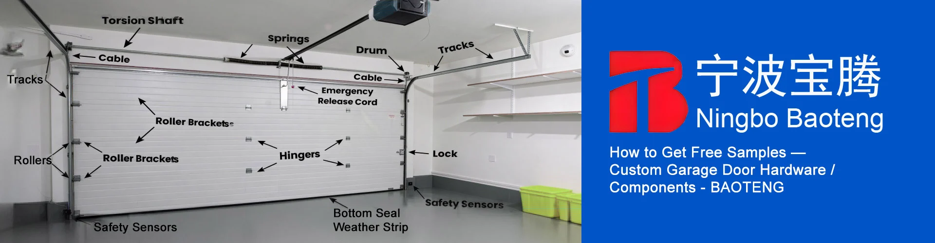
Inside Garage Slide Lock Geometry Checklist
Reference Standard: Relevant material and performance testing standards. For general dimensional inspection and coating evaluation principles, see منظمة ASTM الدولية و ISO standards resources.
Short Answer
For product context and related garage door hardware categories, Baoteng’s main hardware site can be referenced through garage door hardware manufacturing and supply.
When an Inside Garage Lock Is Chosen by Door Geometry, Not by Appearance
A Garage Door Inside Slide Lock, Inside Deadlock is often treated as a small accessory, yet the first selection variable is geometric compatibility. The catalog information identifies lock and latch products in the handle and lock series that are relevant to an inside slide or deadlock function. BT-L701 Industrial Latch Lock is listed with 1.5 mm case thickness, 4 mm bar thickness, and a 103 mm fixing-hole center line. BT-L702 Residential Latch is listed with 1.5 mm case thickness, 4 mm bar thickness, and an 83 mm fixing-hole center line. BT-L704 Industrial Latch is listed with 2.0 mm case thickness, 4.0 mm bar thickness, و galvanized finish.
That difference between 83 mm و 103 mm changes the installation question. A replacement lock is not simply selected because the old part looks similar. The fixing-hole center line determines whether the installer can reuse existing holes, whether new holes may be needed, and whether the lock body will sit in the intended position relative to the internal door edge or track-side receiving point. When the hole line is wrong, the bar can be visually present but mechanically displaced. The result may be a lock that mounts to the panel yet does not travel cleanly into its receiving path.
An edge-case model is useful here. Imagine a door panel that has already been drilled for a lock using an 83 mm fixing-hole center line. If a user tries to replace it with a lock whose mounting expectation is closer to the 103 mm fixing-hole center line route, the mismatch is not only a cosmetic issue. The lock body may be pulled into a forced position, and the slide bar may be shifted from its intended travel line. In the early phase, the user may feel extra resistance during manual sliding. In the middle phase, the repeated hand force may widen or stress the fastened area. At the extreme phase, the lock may still appear mounted, but the bar may no longer meet the receiving zone smoothly enough for reliable daily use.
A cross-dimensional comparison can be made between a residential replacement and an industrial replacement. A residential door more commonly rewards exact hole-line recovery because the door skin is often used as a practical installation surface. An industrial route may tolerate more robust surrounding hardware, yet the lock still depends on alignment. The difference is not that one version is automatically superior. The difference is that BT-L702’s 83 mm fixing-hole center line و BT-L701’s 103 mm fixing-hole center line point to different installation assumptions.
| Geometry Variable | Real Catalog Anchor | Practical Meaning | Risk if Ignored |
|---|---|---|---|
| Residential hole line | 83 mm | Helps identify BT-L702 route | Existing holes may not match another lock body |
| Industrial hole line | 103 mm | Helps identify BT-L701 route | Forced mounting can shift bar travel |
| Lock body thickness | 1.5 mm / 2.0 mm | Affects seating behavior | Uneven fastening may distort fit |
| Slide bar thickness | 4.0 mm | Defines the moving member size | Misalignment can create drag |
The Small Thickness Difference That Changes How the Lock Body Sits on a Door Skin
The case thickness values in the catalog should not be reduced to a simple strong-versus-weak claim. BT-L701 و BT-L702 use a 1.5 mm case thickness, while BT-L704 uses a 2.0 mm case thickness. These numbers matter because the lock body must sit against a garage door surface while remaining stable enough for the slide bar to move without binding. A lock body is not floating in space. It receives hand force, screw clamping force, panel vibration, and the small distortions created by an imperfect door surface.
A 1.5 mm case can be suitable when the mounting area is flat and the hole line is correct. Its behavior depends on even seating and controlled fastening. If the installer tightens the fasteners unevenly over a slightly uneven panel, the case can be encouraged into a minor twist. A 2.0 mm case has a different seating character. It may resist small installation irregularities better, but it still cannot solve a wrong hole line or a distorted receiving path. The catalog data supports the thickness comparison; it does not support claims about steel grade, pull resistance, or certified security rating.
An extreme seating model begins before the first daily use. Initial phase: the lock body is placed on a door skin with a slight ripple or paint build-up. The user tightens one side first, then the other. The case appears flat enough by eye. Middle phase: repeated door vibration and manual locking force cause the lock body to settle into the actual surface profile beneath it. If the seating is uneven, the bar path may feel less smooth. Extreme phase: the lock body remains attached, but its relationship with the bar opening is no longer as neutral as it was during the first installation moment.
A comparison test can be described without inventing unsupported performance data. Place a 1.5 mm case sample and a 2.0 mm case sample on two simulated panel surfaces: one flat and one slightly uneven. Without measuring pull strength or torque, the inspection can still compare practical seating indicators: whether the body rocks before fastening, whether the slide bar moves freely after tightening, whether the visible case edge sits evenly, and whether the hole-line position remains consistent. This is not a laboratory strength rating. It is a practical receiving inspection method based on the known catalog dimensions.
For a factory or buyer, the safer checklist is to separate thickness verification from performance claims. Confirm whether the item is expected to follow the 1.5 مم route or the 2.0 mm route. Confirm whether the sample sits flat before fastening. Confirm whether the bar slides after fastening, not only before fastening. The case does not work alone; it works as a seated surface component attached to a door structure.
Garage Door Inside Slide Lock Bar Movement Checklist
إن 4.0 mm bar thickness should be read as a movement constraint. In a slide lock, the bar is the moving member that must travel through the lock body and enter the receiving area with enough straightness and clearance. The catalog states 4 mm bar thickness for BT-L701 and BT-L702 and 4.0 mm bar thickness for BT-L704. That does not define the full bar length, hardness, stroke, or pull resistance. It does define a critical physical presence: a 4.0 mm moving member must remain aligned with the channel it travels through.
The root mechanism is mechanical tolerance stacking. The lock body position, fixing-hole center line, door panel flatness, track-side location, and receiving point all combine to determine whether the slide movement feels clean. If one variable is off, the user often experiences it as a sticky lock. The bar itself may not be defective. The system around the bar may be guiding it into a biased path. In this sense, a 4.0 mm bar is not only a part dimension. It is a reference for the space the product needs in order to move.
A fatigue-style movement model can be imagined over daily use. Initial phase: the lock is newly installed, and the user needs a little extra force to slide it because the bar path is not perfectly aligned. Middle phase: the operator adapts by pushing harder or lifting the door slightly while locking. The extra behavior hides the alignment problem. Extreme phase: the bar continues to move, but the lock becomes dependent on a specific hand angle or door position. At that stage, the issue is not only comfort. It becomes a repeatability issue.
A cross-system comparison shows why visual inspection alone is weak. One lock may look straight from the front but have a receiving path that is slightly offset. Another may look less polished but slide cleanly because the hole line, case seating, and receiving path are consistent. Since the catalog does not provide stroke length or load data, the responsible article angle is to evaluate movement smoothness, not to claim security strength.
KEY TAKEAWAYS
- A lock that slides smoothly before fastening but drags after fastening may have a case seating or hole-line issue.
- A 4.0 mm bar thickness needs a straight and consistent travel path, not only a visually centered lock body.
- A mismatch between 83 mm و 103 mm fixing-hole routes can shift the bar path even when the lock appears mountable.
A practical movement checklist should include these steps:
- Confirm whether the intended replacement follows the 83 mm أو 103 mm fixing-hole center line route.
- Check the lock body against the door surface before tightening.
- Slide the bar before fastening and again after fastening.
- Watch for drag that appears only after the body is clamped to the door.
- Avoid judging alignment only from the outer shape of the lock.
- Treat repeated hand-force compensation as an early warning sign.
Galvanized Finish as a Storage-and-Handling Boundary Before Installation
The catalog identifies BT-L704 with a galvanized finish. This should be interpreted carefully. Galvanizing can be discussed as a surface finish route, but the catalog does not provide zinc layer thickness, salt spray duration, corrosion class, or outdoor exposure rating. The correct writing boundary is storage and handling logic before installation, not a promise of corrosion performance.
A galvanized surface is still a surface. It can be affected by abrasion during bulk handling, contact marks during transport, moisture trapped inside packaging, and fingerprints or handling residue before installation. In a garage door inside slide lock application, the inside position may reduce direct rain exposure, but it does not remove humidity, condensation, temperature swings, or vibration. If the surface is scratched deeply enough to expose the underlying metal at edges or contact points, corrosion risk can become more localized. The article should state this as general material logic, not as a certified outcome for this product.
An edge-case storage model helps clarify the boundary. Initial phase: galvanized locks are stored in a dry carton, with minimal surface contact. The finish remains visually stable. Middle phase: the carton is moved repeatedly, metal parts rub against each other, and edge marks begin to appear. Extreme phase: the parts are stored in a humid area, condensation forms, and contact areas hold moisture. The risk is not that every galvanized part fails. The risk is that surface protection can be locally compromised before the lock ever reaches the door.
A cross-dimensional comparison can be made between a clean installation path and a rough handling path. In the clean path, the lock is kept dry, separated from heavy abrasion, and inspected before mounting. In the rough path, the lock may arrive with scratches, bent bar ends, or surface staining. The same catalog specification can produce different installation experiences because handling changes the condition of the part before use.
This is where factory-level prevention should stay practical. The factory can manage product identity by separating 1.5 مم و 2.0 mm case routes, checking the 4.0 mm bar thickness, verifying 83 mm و 103 mm hole-line expectations, inspecting galvanized appearance for BT-L704-type products, and packing the locks so that the slide bar is not bent under pressure. None of these steps require unsupported claims. They are grounded in dimensional control and normal hardware inspection logic.
| Inspection Area | Real Data Anchor | Acceptance Logic | What Not to Claim |
|---|---|---|---|
| Case route | 1.5 mm / 2.0 mm | Confirm correct version and visible seating | Do not claim certified load rating |
| Bar route | 4.0 mm | Check straight sliding after fastening | Do not claim cycle life |
| Hole line | 83 mm / 103 mm | Match existing door geometry | Do not assume universal replacement |
| Finish route | Galvanized finish | Inspect visible surface before mounting | Do not claim salt spray hours |
| Packing condition | Catalog-based product handling | Avoid bending and surface abrasion | Do not invent packaging standard |
PRO-TIP / CHECKLIST
- Measure the existing fixing-hole center line before choosing the replacement lock route.
- Confirm whether the needed case route is closer to 1.5 مم أو 2.0 mm.
- Slide the 4.0 mm bar before and after tightening the lock body.
- Inspect the case edge for distortion after mounting on the door skin.
- Keep galvanized-finish parts dry and separated from heavy abrasion before installation.
- Reject any claim of salt spray rating, screw specification, or pull resistance unless the supplier provides documented test data.
الأسئلة الشائعة (FAQ)
How to replace a garage door opener when using an inside slide lock?
Before replacing or operating a garage door opener, make sure any inside slide lock or inside deadlock is disengaged. A locked slide bar can block door movement and create strain. The catalog data supports checking lock geometry and bar movement, not opener compatibility claims.
How to adjust a garage door with an inside slide lock?
Start by checking whether the slide bar travels freely when the door is fully closed. If the bar drags, review the 83 mm أو 103 mm fixing-hole route, case seating, and receiving alignment. Do not force adjustment by bending the bar unless supported by supplier instructions.
Why my garage door won’t open with an inside deadlock installed?
One possible reason is that the inside deadlock remains engaged or the slide bar is partly blocking the door path. A 4.0 mm bar can prevent smooth movement if it is still inside the receiving area. Confirm the lock is fully released before diagnosing the opener or spring system.