Torsion Spring Coupling Inspection Checklist
Reference Standard: Relevant material and performance testing standards for garage door shaft hardware, including dimensional inspection logic, coating review, trial assembly checks, and general fastener engagement verification. For broader engineering context, readers may compare inspection planning with resources from ASTM International and general product safety guidance from the International Door Association.
Short Answer
A Torsionsfederkupplung in this article refers to the closest confirmed catalog data around shaft couplers and torsion spring hardware. The available product boundary includes shaft coupler options with 1 inch inside diameter, 1-1/4 inch inside diameter, 1 inch and 1-1/4 inch matching range, 90mm length, 120mm length, galvanized finish, und aluminum material options. Related torsion spring hardware includes torsion spring dimensions such as 2 Zoll, 2-5/8 inch, 3-3/4 inch, und 5-1/4 inch inside diameter, with wire diameter ranges from 5.0–6.8mm, 6.5–8.0mm, 7.0–10mm, und 7.0–10.5mm, using finishes such as anti-rust oil, galvanized treatment, und electrophoresis.
The article does not invent load ratings, torque values, cycle life, salt spray hours, or certification claims. Instead, it builds a practical checklist around what can be safely checked from the known dimensional and surface-finish boundaries.
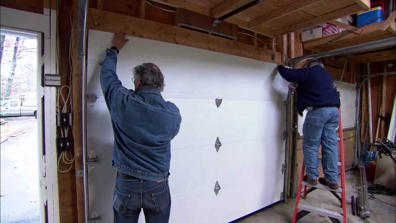
When A Torsion Spring Coupling Leaves The Carton: First Handling Marks Before Installation
A coupling inspection should begin before the part reaches the door shaft. Many installation problems are not caused by the visible shape of the coupling alone; they are caused by small mismatches that become locked into the system during unpacking, sorting, and first placement on the shaft. In the confirmed data boundary, the shaft coupler family includes 1 inch inside diameter, 1-1/4 inch inside diameter, and a 1 inch and 1-1/4 inch matching range. It also includes 90mm und 120mm length options, with either galvanized oder aluminum descriptions depending on the model. These differences are not decorative details. They define how the installer should identify the part before it is handled as a live connection element.
The first inspection layer is packaging friction. A galvanized coupler can arrive with superficial handling marks, but the critical question is whether those marks affect the contact surfaces, threaded areas, or visual model identification. A small rub mark on an external face may be acceptable as a cosmetic trace, while a burr near the bore edge can interfere with shaft insertion. Aluminum options require a different observation habit because the material can show surface impressions more easily. That does not mean the part is defective by default; it means the receiving check should separate ordinary handling marks from deformation around functional zones.
A practical edge-case model is a mixed workshop where multiple door sizes are being assembled in the same area. A carton containing 90mm und 120mm couplers is opened, a galvanized unit is placed near an aluminum unit, and the installer is working under time pressure. The visible shape may look similar, but the length and inside diameter are not interchangeable assumptions. At the initial stage, the risk is not mechanical failure; it is silent misclassification. In the middle stage, the part is trial-fitted and may seem close enough if the shaft enters only partially. At the limit stage, the wrong part may be tightened, creating localized pressure at the wrong contact area and making later troubleshooting much harder.
A cross-dimensional comparison case can be built between two receiving checks. In a weak process, the operator checks only whether the coupler looks complete. In a stronger process, the operator checks model identity, inside diameter, length, surface finish, bore edge condition, und threaded area cleanliness before the part leaves the sorting table. The second process does not require invented testing equipment; it requires disciplined separation of confirmed parameters.
| Receiving Check Point | Confirmed Data Boundary | Practical Risk If Ignored | Safe Inspection Language |
|---|---|---|---|
| Innendurchmesser | 1 inch, 1-1/4 inch, 1 inch and 1-1/4 inch | Shaft fit uncertainty | Confirm bore size before trial assembly |
| Länge | 90mm, 120mm | Wrong part placed in same job area | Separate by model and length |
| Surface description | Galvanized or aluminum | Cosmetic mark confused with functional damage | Inspect contact zones, not only appearance |
| Bore edge | Functional shaft entry area | Burrs or dents may affect insertion | Check for clean entry before tightening |
| Threaded area | Fastener engagement zone | Set screw may not seat consistently | Confirm thread cleanliness and screw entry |
KEY TAKEAWAYS
- Handling marks near the bore edge matter more than shallow marks on non-contact faces.
- Similar 90mm und 120mm couplers should be separated before installers begin work.
- A part that looks visually similar may still differ by 1 Zoll oder 1-1/4 inch shaft fit.
The Small Threaded Area That Decides Whether The Coupling Feels Stable
The threaded area is a small zone, but it controls how the coupler transfers clamping intention into mechanical contact. Because the confirmed product data does not provide set screw size, screw count, torque value, or thread standard, this section must stay within safe engineering language. The practical point is not to claim a precise tightening value. The practical point is to inspect whether the screw enters smoothly, seats consistently, and creates a stable contact mark without forcing the coupling into an uneven position.
At the physical level, a torsion shaft connection is exposed to repeated start-stop movement. A torsion spring stores and releases elastic energy; the shaft and coupler experience small changes in contact pressure as the system moves. If the screw-seat region is clean and aligned, the screw pressure is transferred into a more predictable local contact patch. If the threaded hole contains burrs, coating accumulation, deformation, or contamination, the screw may feel tight before it is fully seated. This false-tight condition is dangerous because the hand feel suggests completion, while the contact interface may still be uneven.
The microscopic mechanism is based on contact pressure and fretting behavior. When two metal surfaces touch under vibration, tiny relative movement can create polished marks, dark residues, or local indentation. A galvanized surface may resist corrosion where the coating remains intact, while a damaged contact point can expose a more vulnerable area. Aluminum may behave differently because its surface can mark or indent under localized pressure, especially if the load is concentrated at a small point. This article does not claim a specific failure threshold; it only identifies the inspection logic that should exist before and after tightening.
A stress timeline model helps explain why this small zone deserves attention. In the initial stage, the screw enters the threaded hole and starts to create contact with the shaft. If the thread is clean, resistance increases gradually. If the hole has debris or coating buildup, the resistance may rise too early. In the middle stage, repeated door movement begins to show whether the contact mark is stable. A consistent seated mark is different from a sliding scratch. In the limit stage, a poorly seated screw can allow tiny rotational movement that spreads into noise, uneven pressure, or visible marking around the coupling surface.
A cross-system comparison can be made between a purely visual check and a functional engagement check. A visual check sees a screw head sitting in place. A functional engagement check asks whether the screw entered smoothly, whether it stopped because of true contact, whether the coupling remained centered, and whether the surface mark after movement stayed localized. The second method creates better information without inventing unverified torque data.
PRO-TIP / CHECKLIST
- Confirm the coupler model before checking the threaded area.
- Inspect the threaded hole for burrs, coating buildup, or visible blockage.
- Check whether the screw enters smoothly before final tightening.
- Review the shaft contact mark after the first controlled movement.
- Separate cosmetic scratches from functional seat damage.
- Do not convert hand feel into a claimed torque value unless measured.
- Record unusual seating resistance for batch-level review.
Mixed-Bin Risk: Similar Couplers Need Separation Before Installation
Mixed-bin risk is one of the least dramatic but most practical problems in torsion spring coupling handling. When several couplers share a similar shape, workers may sort them by appearance rather than by confirmed specification. The confirmed catalog boundary creates several opportunities for confusion: 1 Zoll und 1-1/4 inch inside diameter options, a combined 1 inch and 1-1/4 inch matching description, 90mm und 120mm length options, and both galvanized und aluminum descriptions. These are enough to require physical separation before installation work begins.
The problem develops in stages. At the receiving stage, parts may be correct but stored too closely. At the picking stage, a visually similar coupler may be selected for the wrong shaft condition. At the trial-assembly stage, a wrong or uncertain part may appear close enough if the fitter does not complete the full seating check. At the movement stage, the mistake becomes more expensive to diagnose because the installer may start looking for spring, drum, track, or opener causes when the earliest issue was bin separation.
A useful comparison case is a warehouse that separates couplers by broad category versus one that separates by functional connection requirement. Broad category sorting says all shaft couplers belong together. Functional sorting separates 90mm von 120mm, separates 1 Zoll von 1-1/4 inch, and keeps galvanized and aluminum descriptions traceable to their model identity. The difference is not about adding bureaucracy; it is about preventing a specification error before it becomes an installation problem.
The edge extreme scenario is a rush order for multiple garage door, industrial door, commercial door, or residential door hardware packages. A worker opens several cartons, removes protective wrapping, and places couplers in a shared metal bin. If the parts are later picked by appearance alone, the original carton identity has already been broken. In the initial phase, no mechanical issue exists. In the middle phase, the wrong part may be installed but not yet obviously problematic. In the final phase, the system shows noise, uneven movement, or rework demand, and the team loses the ability to trace the original selection decision.
| Sorting Variable | Weak Control Method | Stronger Control Method | Benefit |
|---|---|---|---|
| Länge | Store all similar couplers together | Separate 90mm und 120mm parts | Reduces wrong-length selection |
| Bore size | Check only by visual shape | Confirm 1 Zoll oder 1-1/4 inch fit | Reduces shaft mismatch risk |
| Material or finish | Treat all silver parts the same | Keep galvanized and aluminum identity visible | Reduces finish-related confusion |
| Picking process | Installer selects from mixed bin | Installer selects from labeled batch group | Improves traceability |
| Pre-install review | Fit by hand only | Verify model, bore, length, and screw entry | Catches errors earlier |
This article intentionally avoids the older angle of procurement messaging or SKU naming control. The stronger angle is operational: how similar couplers move through bins, cartons, workbenches, and installation zones before anyone notices a mismatch.
Garage Door Torsion Spring Coupling First-Movement Review
The first movement after installation is not a laboratory proof test, and it should not be written as a load-rating claim. It is a controlled observation stage. The available data supports a safe review around garage doors, industrial doors, commercial doors, and residential doors because the catalog context places torsion spring hardware and shaft couplers within door hardware systems. It does not support claims about door weight, cycle rating, torque rating, spring life, or specific safety certification.
A first-movement review should observe the coupling as a connection point. The reviewer can look for shaft movement relative to the coupling, new marks around the screw-seat area, unexpected axial shift, unusual sound at the shaft line, or a visible change in the coupler’s position. These observations are useful because they connect the installation event to early mechanical behavior without exaggerating the meaning of the check. A stable first movement does not prove lifetime performance. An unstable first movement does show that a second check is needed before the system is treated as complete.
The physical mechanism is easy to underestimate. A torsion spring system does not apply a static condition forever; it changes state as the door opens and closes. The coupling experiences repeated contact pressure, micro-vibration, and alignment demand. If the bore fit, screw engagement, and surface seat are consistent, the first movement should leave no obvious sign of slipping. If the contact is uneven, the first movement may produce a new mark, a slight shift, or an audible clue. These clues should be recorded as observation items, not converted into unverified engineering claims.
A cross-dimensional comparison helps clarify the difference between safe review and overclaiming. A weak review says the door moved, so the coupling is approved. A stronger review says the door moved, the coupling position was checked, the screw-seat area was reviewed, no new unexpected mark was observed, and no abnormal shaft-line sound was recorded during the first controlled movement. This language is more useful because it creates a repeatable inspection habit without inventing data.
For practical sourcing and maintenance context, readers can also review related garage door hardware and system solutions to understand how shaft couplers, torsion springs, brackets, tracks, cable drums, and other door components sit within a broader hardware environment.
Solutions And Standards For A Safer Coupling Review
A useful inspection checklist must translate the confirmed product boundary into repeatable work. The known data supports four solution layers: dimensional confirmation, threaded-hole engagement review, surface-condition separation, and first-movement observation. Each layer reduces uncertainty in a different way.
Solution 1: Dimensional confirmation before trial assembly.
Execution Protocol: Before the coupler is moved to the installation point, confirm whether it belongs to a 1 Zoll, 1-1/4 inch, oder 1 inch and 1-1/4 inch fit group. Confirm whether the required coupler length is 90mm oder 120mm. This should happen at the receiving or picking stage, not after the part is already on the shaft.
Material expected behavior: A correctly matched bore should allow controlled shaft entry without forcing, rocking, or uncertain seating. The material does not become stronger through this step; the improvement is in fit accuracy and reduced risk of uneven local pressure.
Hidden cost and side-effect control: The added time can look inefficient in a busy warehouse. The countermeasure is to combine bore and length confirmation with picking, so inspection becomes part of normal material flow rather than a separate bottleneck.
Solution 2: Threaded-hole and set-screw engagement review.
Execution Protocol: Check that the threaded hole is visibly clear and that the screw enters smoothly before final clamping. Do not claim a torque value unless a measured process exists. Use hand-feel observations only as a screening step, then review the seated contact area after initial movement.
Material expected behavior: Clean engagement reduces false-tight conditions. The contact zone is more likely to create a localized seat rather than a sliding mark. Galvanized and aluminum surfaces may show different marking behavior, so the inspector should observe the functional zone rather than judge by color alone.
Hidden cost and side-effect control: Overchecking every cosmetic mark can slow the process. The control method is to prioritize functional areas: bore edge, threaded hole, screw seat, and shaft contact region.
Solution 3: Finish-aware storage and handling.
Execution Protocol: Keep galvanized and aluminum couplers traceable to their model identity. Do not mix visually similar parts after carton removal. If handling marks appear, classify them by location and depth rather than by appearance alone.
Material expected behavior: Galvanized surfaces provide corrosion-related protection where the coating remains intact. Aluminum surfaces may resist ordinary corrosion but can show localized pressure marks. The expected improvement is fewer misread handling marks and cleaner final selection.
Hidden cost and side-effect control: Separate storage may require more bins or labels. The benefit is reduced rework caused by wrong selection or uncertain finish identity.
Solution 4: First-movement observation record.
Execution Protocol: After the first controlled door movement, check the coupling position, screw-seat marks, shaft-line noise, and visible shift. Record only what can be observed. Do not turn a first-movement review into a lifetime performance claim.
Material expected behavior: A stable connection should not show sudden position change or new sliding marks after the first controlled movement. Any visible change should trigger a second look at bore fit, screw engagement, and part identity.
Hidden cost and side-effect control: A first-movement review adds a short step after installation. The risk of skipping it is higher because early clues may disappear once the system is used repeatedly.
| Control Layer | Data Used | Common Test Basis | Expected Practical Result |
|---|---|---|---|
| Bore confirmation | 1 inch, 1-1/4 inch, 1 inch and 1-1/4 inch | Gauge or trial-fit inspection | Lower mismatch risk |
| Length separation | 90mm, 120mm | Dimensional check | Cleaner model selection |
| Surface review | Galvanized or aluminum | Visual and functional-zone inspection | Better handling-mark classification |
| Threaded-hole review | Screw engagement zone | Entry feel and seat observation | Reduced false-tight risk |
| First-movement review | Installed coupling behavior | Controlled movement observation | Earlier detection of shift or mark change |
| Batch traceability | Model and carton identity | Picking and storage discipline | Reduced mixed-bin uncertainty |
Häufig gestellte Fragen (FAQ)
How much does it cost to replace garage door springs?
The cost depends on spring type, door size, labor, and local service conditions. A coupling inspection is separate from spring replacement pricing, but related shaft hardware should be checked when torsion springs are serviced.
How long does a garage door spring last?
Spring life depends on spring design, cycle use, door balance, environment, and maintenance. This article does not claim a cycle rating. During spring service, the shaft coupling should be checked for fit, set screw seating, and surface condition.
Where can I buy garage door springs?
Garage door springs and related shaft hardware are usually purchased from garage door parts suppliers, installers, or door hardware manufacturers. Buyers should confirm spring dimensions, shaft size, and compatible coupling specifications before ordering.
How to open a garage door without electricity?
Use the manual release only if the door is properly balanced and safe to move. If a torsion spring, shaft, or coupling problem is suspected, do not force the door; contact a qualified technician.
How to reset a Genie garage door opener?
Reset steps vary by opener model. Follow the opener manufacturer’s manual. A reset will not correct a mechanical issue such as an unstable torsion shaft coupling, worn hardware, or incorrect spring balance.
How to reset a MyQ garage door opener?
Use the MyQ app and the manufacturer’s instructions for your device. If the door moves unevenly after reset, inspect mechanical parts such as springs, drums, shaft couplers, and tracks before assuming the issue is digital.
How to repaint a garage door?
Clean the surface, remove loose paint, prime if needed, and use suitable exterior paint. Painting does not address torsion spring or coupling performance, so mechanical hardware should be inspected separately.