
Center Bearing Support Bracket Checklist
Étalon de référence : Relevant material and performance testing standards, including general corrosion evaluation principles from ASTM International and mechanical fastener verification concepts aligned with ISO standards information.
Réponse courte
Seasonal Temperature Drift Around The Center Bearing Seat
A garage door bearing bracket is usually judged by visible geometry: plate thickness, hole location, bearing center distance, and surface finish. That view is useful, but it misses a slower condition: seasonal temperature drift around the center bearing seat. A center support point can appear aligned during installation, then behave differently after cold mornings, warm afternoons, damp nights, and repeated torsion shaft movement.
The available catalog data identifies several relevant bearing bracket configurations: 2.5mm residential bearing brackets, 2.5mm and 4.0mm bearing bracket options, 4.0mm industrial bearing brackets, 85mm bearing center distance, and industrial center distances including 110mm, 123mm, 148mm, and 185mm, all with finition galvanisée. The material grade is not specified, so the correct engineering approach is not to invent a steel grade. The useful checklist is to treat these dimensions as the fixed reference points around which thermal movement and alignment behavior must be assessed.
Metal expands and contracts slightly as temperature changes. In normal garage door hardware, that movement is small, but it is not meaningless. The bracket plate, bearing seat, torsion shaft, fasteners, and wall-side mounting surface do not always respond at the same rate. If the bracket is thinner, such as a 2.5mm residential bracket, it may transmit small plane changes more visibly than a heavier 4.0mm industrial bracket, especially when the supporting wall or mounting surface is uneven. This does not mean a 2.5mm bracket is wrong; it means it belongs in a checklist where the working environment, door duty, and shaft support requirement are matched to the bracket format.
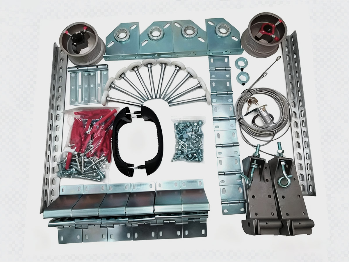
A practical edge-case model is a seasonal garage that moves from damp cold storage conditions to a warmer daytime operating state. At the initial stage, the shaft and bearing seat may produce slightly different contact behavior than they do after several cycles. At the middle stage, the bracket plane and fastener pressure settle into the repeated movement pattern. At the stress stage, any existing small mismatch in bearing seat alignment may become more noticeable through running noise, uneven rotation feel, or repeated need for adjustment. The catalog dimensions do not provide temperature limits, so the model should stay qualitative, but it remains physically reasonable.
A cross-dimensional test case compares a residential 85mm bearing center distance bracket with an industrial bracket using 110mm to 185mm bearing center distances. The residential setup is usually judged by compact mounting geometry and ordinary garage door use. The industrial setup may place more emphasis on wider support geometry and stronger stiffness expectations. The test is not about saying one is universally stronger for every condition. It is about asking whether the bracket, shaft, bearing seat, and mounting surface stay in the same working relationship after temperature-driven dimensional changes and repeated travel.
A useful checklist question is simple: after a seasonal temperature swing, does the center support still behave like a stable bearing reference, or does it become a point where rotation feel changes? That question opens a more precise inspection path than only asking whether the bracket looks bent.
Cold Start Rotation Versus Warm Operating Alignment
Cold start behavior is an overlooked part of bearing bracket inspection. A door may rotate differently during the first movement of the day than it does after several cycles. That difference can come from lubricant condition, shaft surface temperature, bearing contact, fastener pressure, or small changes in how the bracket plane interacts with the shaft axis. A universal bearing bracket used as a center support should be checked in both states when the door system has shown repeated noise, shaft runout, or alignment complaints.
The key technical distinction is between static alignment et operating alignment. Static alignment is what appears correct when the door is not moving. Operating alignment is what happens when the torsion shaft rotates under load, the bearing seat receives contact pressure, and the support bracket resists movement. A bracket with 85mm bearing center distance can look correct in a residential installation, while a larger industrial geometry using 110mm to 185mm center distances can look correct in a heavier system. Yet both need verification under movement, because the shaft does not care about catalog classification once rotation begins; it follows the combined accuracy of center distance, seat position, mounting plane, and fastener stability.
The edge-case model here is a cold-start test followed by a warm-running comparison. During the initial phase, the inspector observes whether the shaft rotation begins smoothly without a sharp change in sound. During the working phase, after repeated opening and closing, the inspector checks whether the same bracket area becomes louder, warmer to the touch, or visually unstable. During the limit phase, repeated inconsistency between cold and warm operation suggests that the issue is not only a surface-level sound. It may indicate that the bearing seat and support plane are responding differently once the system has moved through several cycles.
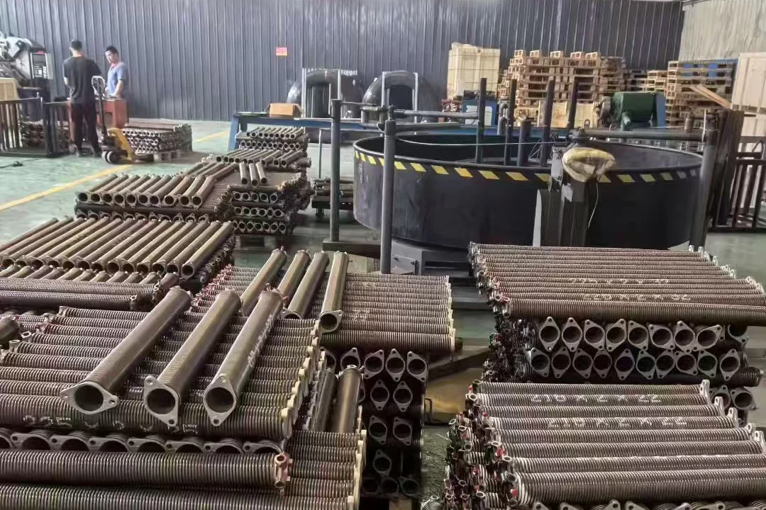
A practical comparison test can be done without inventing unsupported numbers. The residential case uses an 85mm bearing center distance as the reference geometry. The industrial case uses the catalog’s broader bearing center distance range of 110mm, 123mm, 148mm, or 185mm. For each setup, the same questions are asked: Does the shaft remain visually centered through rotation? Does the bearing seat appear to load evenly? Does the support bracket plane stay still when the door begins moving? Does the sound change after several cycles? This comparison avoids repeating a simple size-selection narrative. It looks instead at how each geometry behaves through temperature state and movement state.
| Inspection State | Residential Reference | Industrial Reference | Practical Acceptance Logic |
|---|---|---|---|
| Static visual check | 85mm center distance | 110mm to 185mm center distance | Bearing seat should appear centered without visible bracket twist |
| First cold movement | 2.5mm or 2.5mm and 4.0mm formats | 4.0mm bracket format | Rotation should begin without sudden noise change |
| Repeated warm operation | Galvanized bearing bracket surface | Galvanized industrial bracket surface | No progressive looseness or visible plane movement |
| Post-cycle review | Residential bearing support area | Industrial shaft support area | Sound and contact should remain consistent |
| Maintenance trigger | Noise, shaft jump, or fastener movement | Noise, shaft jump, or fastener movement | Inspect bracket plane, bearing seat, and mounting pressure |
POINTS CLÉS À RETENIR
- A bracket can look aligned when static but behave differently during cold-start rotation.
- Repeated noise after several cycles may point to operating alignment, not only surface wear.
- A change in bearing seat contact after temperature shifts is an early reason to inspect bracket plane stability.
Galvanized Surface Behavior Under Temperature And Humidity Cycling
The catalog identifies finition galvanisée as the surface condition for the relevant bearing bracket entries. That is a real product detail and should be used carefully. It should not be exaggerated into unsupported claims about corrosion hours, coating thickness, or a named performance grade. A more accurate checklist is to ask how galvanized surface behavior changes the way maintenance teams read the environment around the bracket.
Temperature and humidity cycling create a repeating boundary condition. A bracket can cool down, collect moisture, dry again, and then return to movement. If the galvanized surface is intact, it helps provide a protective boundary between the metal substrate and mild corrosive exposure. If the surface has scratches, burrs, exposed cut edges, or damage around holes, those areas become more informative inspection points. The issue is not whether every mark is a failure. The issue is whether marks appear in zones that also experience movement, fastener pressure, or bearing seat contact.
The edge-case model here is a damp garage near a frequently opened door. In the early phase, condensation appears near metal hardware, but the bracket remains visually stable. In the middle phase, repeated wet-dry cycling leaves more visible discoloration near fasteners, holes, or edges. In the stress phase, if the same area also shows movement marks, burr exposure, or a change in running sound, the maintenance priority rises. No unsupported corrosion rating is needed to make this useful. The physical logic is enough: moisture, exposed metal, and repeated mechanical contact increase inspection relevance.
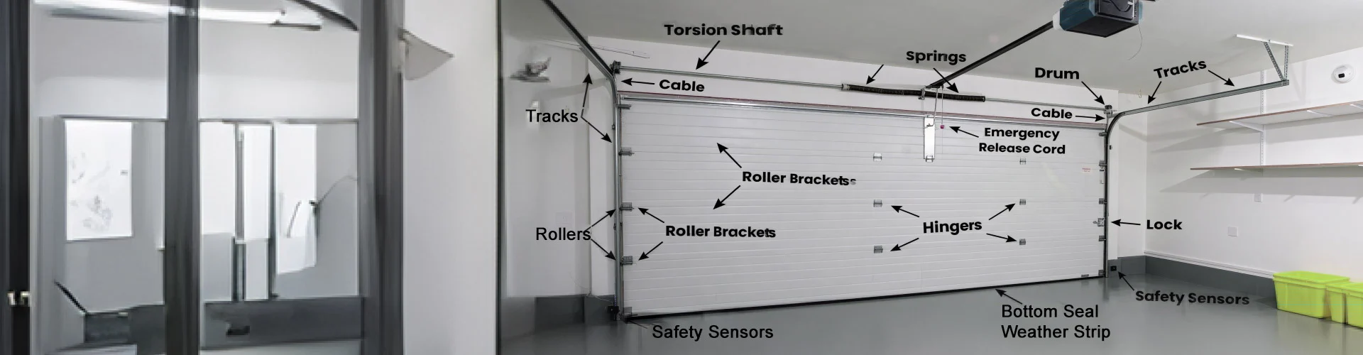
A cross-dimensional comparison test pairs surface review with mechanical review. One bracket may show minor cosmetic surface marks but remain mechanically stable. Another may show surface damage around a bearing opening or mounting hole while also producing noise after seasonal change. The second condition is more important because surface condition and mechanical movement are no longer isolated. This is the correct way to avoid a weak visual-only inspection. The galvanized finish is not treated as a decorative attribute; it is treated as a maintenance signal when combined with thermal cycling, moisture exposure, and movement history.
Practical quality control should stay grounded. Since the catalog does not state a dedicated QC standard, the reasonable inspection set includes plate thickness measurement, bearing center distance measurement, hole diameter and position review, bend angle and flatness check, bearing fit and concentricity review, galvanized surface inspection, burr and sharp-edge control, trial assembly, and batch sampling where appropriate. If corrosion behavior is critical for a project, external test planning can be aligned with recognized corrosion-testing references from ASTM International, but the article should not claim that the catalog itself states a specific salt-spray duration.
Center Bearing Support Bracket Thermal Checklist
A useful final checklist separates reversible thermal movement from real mechanical misalignment. A seasonal sound change is not automatically a bracket defect. A slightly different first movement on a cold day is not always a failure signal. The inspection concern grows when the same symptom repeats, moves into the bearing seat area, appears with bracket plane movement, or leaves visible evidence around holes, fasteners, or galvanized surface boundaries.
The bracket data provides a practical boundary. 2.5mm bracket thickness belongs in the checklist as a residential or lighter reference point. 4.0mm bracket thickness belongs in the checklist as a stronger industrial reference point. 85mm bearing center distance is a key compact bearing geometry. 110mm, 123mm, 148mm, and 185mm industrial bearing center distances provide wider industrial references. Finition galvanisée provides the surface condition that must be inspected under humidity and handling exposure. None of these values should be used as universal promises. They should be used as structured inspection anchors.
A four-part solution system can reduce risk.
1. Temperature-state inspection protocol.
Execution Protocol: Inspect the door once before operation and again after several cycles. During the first check, observe the bracket plane, shaft position, fastener seating, and visible bearing seat relationship. During the second check, listen for noise change, look for bracket movement, and compare the shaft’s apparent rotation path. This separates a static geometry check from an operating geometry check.
Material expectation: The metal bracket should not show visible plane movement or new distortion between the two states. The galvanized surface should remain stable in appearance except for normal handling marks. The expected measurable focus is not a claimed thermal expansion value, but consistency of bracket position, bearing seat contact, and fastener pressure after repeated motion.
Hidden cost and prevention: This protocol costs time because it requires checking the same hardware twice. The risk is over-interpreting harmless seasonal sound. Prevent that by recording whether the sound appears with visible movement, shaft jump, or surface change.
2. Center distance verification before installation.
Execution Protocol: Confirm whether the application requires 85 mm, 110mm, 123mm, 148mm, ou 185mm bearing center distance. Match the bracket to the installation layout before tightening fasteners. Avoid using slotted or forced positioning to compensate for the wrong center distance.
Material expectation: Correct center distance reduces forced bearing seating and avoids unnecessary side pressure. The bracket plate should carry load through its intended geometry rather than through a distorted mounting condition.
Hidden cost and prevention: The hidden cost is inventory complexity, because several center distances may need to be stocked. Prevent confusion by labeling brackets by center distance and thickness before they reach the installation area.
3. Thickness matching by duty condition.
Execution Protocol: Use 2,5 mm formats where the installation environment and door duty fit residential expectations. Use 4,0 mm industrial bracket formats when higher stiffness is required by the project context. Do not treat thickness as the only specification; pair it with center distance and bearing seat fit.
Material expectation: A thicker bracket generally provides better resistance to visible plate movement under comparable geometry, but the actual performance still depends on hole accuracy, mounting flatness, fastener condition, and bearing fit.
Hidden cost and prevention: Over-selecting thickness can raise cost and complicate fit. Under-selecting thickness can increase maintenance frequency. Prevent both by using the door type, cycle expectation, and shaft support requirement as a combined decision.
4. Surface and burr control during receiving inspection.
Execution Protocol: Inspect galvanized surface condition, hole edges, bends, and contact points before assembly. Remove parts with severe deformation, sharp burrs, or visible surface damage in working contact zones. Use trial assembly to confirm that the bearing seats without forced alignment.
Material expectation: A clean hole edge and stable galvanized surface reduce local stress concentration and lower the chance of moisture reaching exposed metal at critical contact zones.
Hidden cost and prevention: Rejecting parts too aggressively can waste usable inventory. Prevent this by separating cosmetic marks from working-zone damage, then escalating only when marks appear near holes, bearing seats, edges, or fastener contact areas.
CONSEIL DE PRO / LISTE DE VÉRIFICATION
- Confirm the required bearing center distance before the bracket reaches the installation site.
- Compare cold-start rotation with warm-running alignment instead of judging only the static position.
- Match 2,5 mm ou 4,0 mm bracket thickness to door duty and support requirement.
- Inspect galvanized finish near holes, bends, and bearing contact zones.
- Check hole edges for burrs before installing the bearing.
- Recheck fastener seating after several door cycles when seasonal sound appears.
- Treat repeated shaft jump or bracket plane movement as a stronger warning than isolated noise.
Foire aux questions (FAQ)
How to install a garage door with a center bearing support bracket?
Install the bracket only after confirming the required bearing center distance, bracket thickness, mounting plane, and shaft alignment. The support point should allow the torsion shaft to rotate without forced bearing contact. If the bracket pulls the shaft off-axis during tightening, stop and recheck the bracket position.
How much does a new garage door cost when hardware needs replacement?
The door cost depends on size, panel type, spring system, labor, and hardware condition. Bearing brackets are only one part of the system. If the shaft support, springs, cables, or track also need service, the total cost can rise beyond a simple panel replacement.
How to change a garage door opener if the bracket area is noisy?
Do not treat opener replacement as the first answer to bracket-area noise. Inspect the torsion shaft, bearing seat, center support bracket, fasteners, and mounting surface first. An opener may sound stressed because the door hardware is binding or rotating inconsistently.
How to set up a garage door opener after hardware inspection?
Set up the opener only after the door moves smoothly by manual operation. If the center bearing support bracket creates shaft resistance, opener setup can mask the real issue and increase strain. Confirm balanced travel, stable shaft rotation, and no bracket movement before final opener adjustment.
How to sync a garage door opener to a car after mechanical checks?
Syncing the opener to a car is an electronic step, not a mechanical fix. Complete bracket, bearing, shaft, and door travel checks first. Once the door operates smoothly and the opener responds correctly, follow the opener manufacturer’s remote or vehicle pairing procedure.
 English
  Русский
  日本語
日本語  한국어
한국어  Français
  Deutsch
  العربية
  Português
  Español