Evaluating center bearing support bracket for precise garage door track alignment
Ensuring the stability and alignment of garage door tracks depends on the correct use of the center bearing support bracket and universal bearing bracket. By focusing on these components, planners can minimize wear, reduce rolling resistance, and achieve reliable structural support for long-term garage door performance.
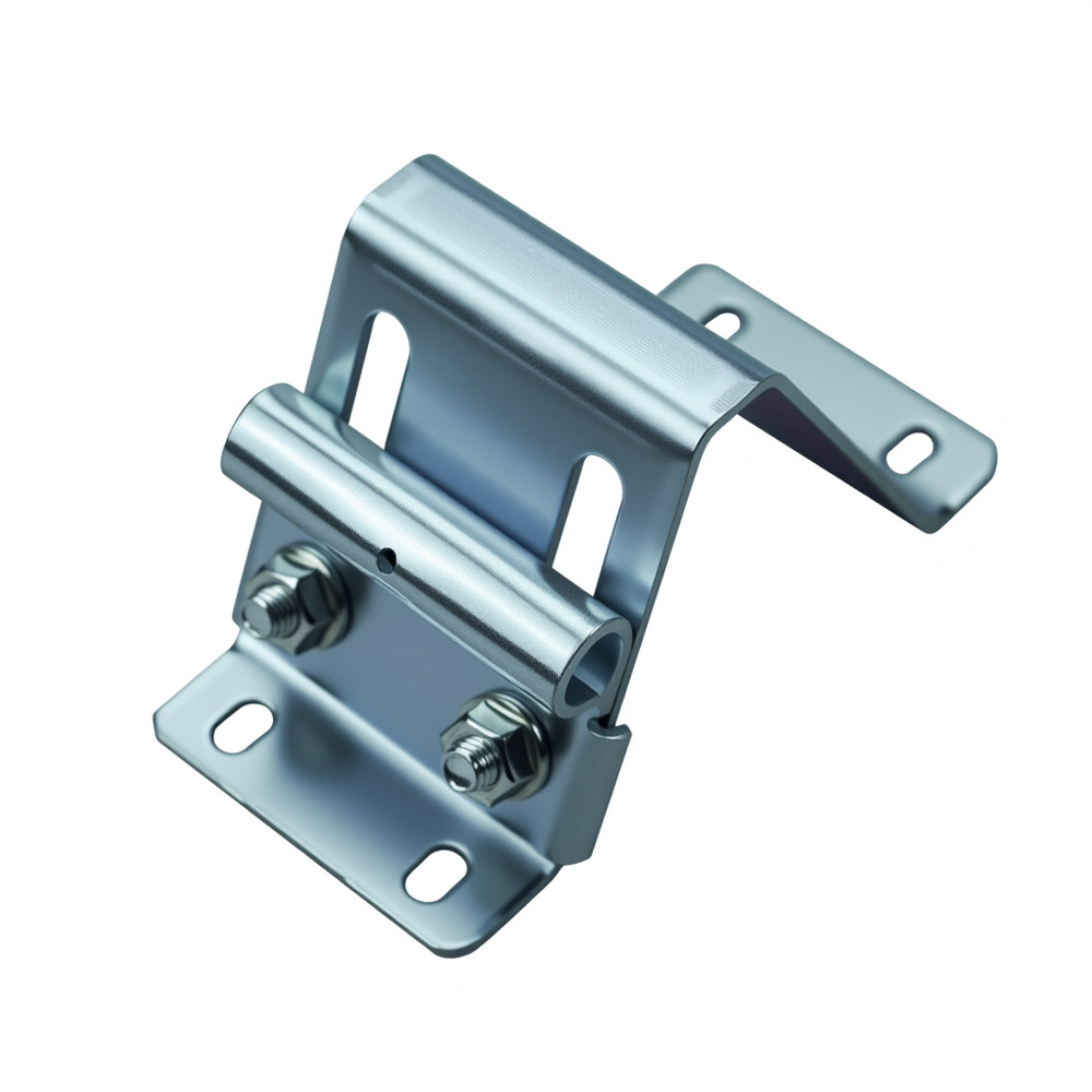
Engineering principles of center bearing support bracket and universal bearing bracket
In garage door assemblies—particularly those utilizing torsion spring mechanisms—the precision and stability of the center bearing support bracket, as well as the universal bearing bracket, are central to ensuring reliable door movement and minimizing operational resistance. Installation planners focused on track alignment and bearing support frequently encounter the challenge of alignment deviation, which can lead to increased component wear and heightened rolling resistance. Addressing these issues requires a methodical understanding of the structural roles these brackets play, the engineering principles governing their function, and the correct methods for their installation and verification. This article, authored from the perspective of a seasoned door system designer, explores the mechanical and structural dynamics of center and universal bearing brackets, emphasizing alignment precision and bearing-stability engineering throughout each phase of system integration.
Garage door track assemblies are subject to significant torsional and radial forces during operation. The center bearing support bracket and universal bearing bracket serve as critical load-bearing interfaces, transferring these forces from the torsion shaft to the supporting structure while maintaining the shaft’s alignment. Misalignment or insufficient rigidity in these brackets can introduce eccentric loads, leading to non-uniform wear patterns on bearings, increased friction during rolling, and, ultimately, premature failure of both the bracket and associated hardware.

The core pain point for installation planners is the tendency for alignment deviation to propagate through the system when bracket installation is imprecise or when bracket rigidity is compromised. Such deviations can manifest as shaft sag, uneven bearing loading, or lateral displacement of the door panels, all of which increase operational resistance and reduce the service life of moving components. The universal bearing bracket, designed to accommodate a range of mounting scenarios, must be selected and installed with equal attention to alignment and load distribution to prevent similar problems.
Methods for ensuring alignment and stability with center bearing support bracket
A robust understanding of the mechanical principles governing these brackets is essential for achieving optimal system performance. The center bearing support bracket is typically fabricated from high-strength steel or galvanized sheet metal, engineered to resist both bending and torsional deformation. Its geometry is designed to cradle the bearing securely, maintaining concentricity with the torsion shaft under both static and dynamic loads. The universal bearing bracket, by contrast, often features slotted mounting holes and adjustable flanges, enabling its use in varied structural configurations while still demanding precise shaft alignment.
- Structural Rigidity: The bracket’s resistance to bending and twisting is directly related to its material thickness, cross-sectional geometry, and mounting method. Insufficient rigidity allows micro-movements under load, leading to cumulative misalignment over time.
- Alignment Precision: The bracket must position the bearing such that the shaft axis remains collinear with the door track plane. Even minor angular deviations can introduce side loads on the bearing, increasing rolling resistance and wear.
- Load Path Integrity: The bracket must transfer forces from the shaft to the supporting wall or header without introducing stress concentrations or points of flexure that could compromise the assembly.
- Compatibilité : Universal bearing brackets must accommodate a range of shaft diameters and wall thicknesses without sacrificing alignment or rigidity.
Installation planners must approach bracket selection and placement with a focus on minimizing the risk of alignment deviation. The following methods, grounded in bearing-stability engineering, are recommended for ensuring precise installation and long-term reliability:
- Pre-Installation Assessment
- Structural Survey: Inspect the mounting surface for flatness, perpendicularity to the shaft axis, and absence of deformation. Any irregularities should be corrected prior to bracket installation.
- Bracket Selection: Choose a center bearing support bracket or universal bearing bracket with material specifications and geometry appropriate for the anticipated load. Reference ANSI/DASMA 102-2015 Section 4.3 for guidance on bracket load ratings and material standards.
- Alignment Procedures
- Shaft Positioning: Use a laser level or precision straightedge to establish the intended shaft axis, ensuring alignment with the door track and end bearing plates.
- Bracket Placement: Temporarily position the bracket and bearing assembly on the shaft, verifying concentricity and perpendicularity before marking anchor points.
- Fastener Selection: Employ high-shear-strength fasteners, such as grade 5 or higher bolts, and ensure proper embedment into structural members.
- Installation Execution
- Progressive Tightening: Secure the bracket using a cross-pattern tightening sequence to prevent angular distortion.
- Bearing Seating: Confirm that the bearing is fully seated within the bracket cradle, with no axial play or misalignment.
- Torque Verification: Apply manufacturer-recommended torque values to all fasteners, as under- or over-tightening can induce bracket deformation or slippage.
- Post-Installation Validation
- Shaft Rotation Test: Manually rotate the shaft to detect any resistance or binding, which may indicate misalignment.
- Operational Cycle Test: Run the door through several full open-close cycles, monitoring for smooth rolling and absence of abnormal noise or vibration.
- Periodic Inspection: Implement a maintenance schedule to recheck bracket integrity and alignment, particularly after high-cycle operation or impact events.
- Common Sources of Alignment Deviation and Engineering Countermeasures:
- Bracket Flexure: Thin-gauge brackets may flex under load, shifting the bearing axis. Countermeasure: Specify brackets with increased material thickness or reinforcement ribs.
- Improper Mounting Surface: Uneven or non-orthogonal surfaces introduce angular misalignment. Countermeasure: Shim or machine the mounting surface to achieve true alignment.
- Fastener Loosening: Vibration or cyclic loading can loosen fasteners, allowing bracket movement. Countermeasure: Use lock washers, thread-locking compounds, or double-nut arrangements.
- Universal Bracket Over-Adjustment: Excessive use of slotted holes can compromise rigidity. Countermeasure: Limit slot extension and reinforce with backing plates where necessary.
Bearing-Stability Engineering: Material and Design Considerations
Material selection for both center and universal bearing brackets is a critical determinant of structural performance. High-carbon or alloy steels are preferred for high-cycle or heavy-duty applications due to their superior yield strength and fatigue resistance. Galvanized coatings provide corrosion protection, essential for installations in humid or corrosive environments. The bracket’s geometry—particularly the width, depth, and presence of gussets or ribs—directly influences its moment of inertia and resistance to deflection.
For universal bearing brackets, the design must balance adjustability with rigidity. Overly long slots or insufficient flange thickness can lead to bracket “creep” under load, gradually shifting the bearing axis and introducing alignment deviation. Engineering best practice dictates that adjustability features be sized only as large as necessary for installation tolerances, with reinforcement provided at high-stress points.
Performance Implications of Alignment Deviation
Alignment deviation in the bearing support system manifests as increased rolling resistance, uneven wear on the torsion shaft and bearings, and, in severe cases, binding or jamming of the door panels. These effects are particularly pronounced in wide or heavy sectional doors, where even minor misalignments are magnified across the span of the assembly. From a bearing-stability engineering perspective, the cumulative effect of small deviations can result in a nonlinear increase in operational resistance, accelerating component fatigue and reducing system lifespan.
Summary: Comparative testing of torsion shaft rolling resistance with 0.5°, 1.0°, and 2.0° bracket misalignment.
Result: Rolling resistance increased by 11% at 1.0° deviation and 27% at 2.0° deviation. Shaft surface wear accelerated proportionally. Conclusion: Alignment precision within 0.5° is critical for optimal bearing performance.
Verification and Compliance
Installation planners should reference recognized standards to ensure that bracket selection and installation methods meet industry requirements. The ANSI/DASMA 102-2015 and relevant EN 13241-1 standards provide authoritative guidance on material properties, load ratings, and installation tolerances for garage door hardware components.
- Verify that all bearing support brackets are specified and installed to maintain shaft alignment within 0.5° of the intended axis.
- Select brackets with sufficient thickness, reinforcement, and corrosion protection for the application environment.
- Employ precision alignment tools during installation and conduct post-installation validation cycles.
- Reference ANSI/DASMA and EN standards for bracket selection and installation procedures.
- Implement periodic inspection protocols to detect and correct alignment deviation before it leads to increased wear or operational resistance.
Achieving structural reliability with center bearing support bracket and universal bearing bracket
For installation planners, the systematic application of bearing-stability engineering principles to the selection, installation, and verification of center bearing support brackets and universal bearing brackets is essential to mitigate the core pain point of alignment deviation. By adhering to the outlined methods and referencing authoritative standards, planners can ensure that garage door assemblies achieve the required structural rigidity and alignment precision, resulting in reduced wear, lower operational resistance, and extended service life.
Reviewed by Senior Garage Door Hardware Engineer