
購入者向け「プッシャープレート」の詳細解説
参照標準: Relevant material and performance testing standards may include ISO 1461 for hot-dip galvanized coatings where the coating process matches the standard そして ASTM A123/A123M for zinc coatings on iron and steel products when applicable. The catalog data confirms only Pusher adjustable Plate, 厚さ4.0mmそして Finish: Galvanized; it does not state the steel grade, hole spacing, tensile strength, coating thickness, or salt-spray rating.
短答
From Loose Adjustment to Controlled Push: Why a 4.0mm Galvanized Pusher Plate Must Be Read as a Positioning Part, Not Just a Flat Bracket
The first mistake in evaluating a pusher adjustable plate is treating it as a passive flat piece of metal. A plain flat bracket only holds position; a Pusher adjustable Plate participates in positioning behavior. It sits in a hardware environment where door movement, installer adjustment, bolt compression, and repeated push direction can all meet at the plate surface. The catalog confirms three usable facts: the product name is Pusher adjustable Plate, the plate thickness is 4.0mm, and the finish is galvanized. Those three facts are enough to shape a serious inspection logic without inventing unsupported parameters.
A 4.0mm galvanized pusher plate has more structural identity than a light sheet cover, but thickness alone does not guarantee correct field behavior. When a plate is used near an adjustable connection, the practical question is not only whether the metal is present. The real question is whether the part can keep its installed position while the surrounding door hardware is repeatedly loaded, released, and slightly shifted during operation. In a garage or industrial door system, even small movement can gradually change how pressure is transferred through mounting holes and contact faces.
The edge extreme scenario model starts with a simple condition: a plate is installed in a slightly misaligned push path where the contact direction is not perfectly square to the plate face. In the initial stage, the plate appears normal because the 4.0mm thickness resists visible bending under ordinary handling. In the middle stage, the bolt contact area begins to carry uneven pressure; the pusher plate may still look acceptable, but the active load zone moves toward one side of the hole or edge. In the limit stage, the issue may show as elongated contact marks, repeated readjustment, noisy movement, or local zinc damage near the working edge. This model does not require a claimed load rating; it follows from basic contact mechanics and repeated mechanical movement.
A cross-dimensional comparison test can separate a useful plate from a visually similar one. In the first sample group, the buyer checks only the front surface and confirms that it is galvanized. In the second sample group, the buyer checks thickness, flatness, edge burrs, hole access, and whether a bolt can be seated without forcing the plate sideways. Both groups may look similar in photos, but only the second test connects the product to its real job: maintaining controlled push alignment. The difference is not cosmetic. It is the difference between a part that passes a quick visual review and a part that can be assembled with fewer adjustment surprises.
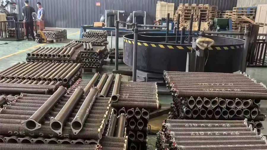
For procurement teams comparing garage door bracket plate options, the safer language is evidence-based: ask whether the item is the specified Pusher adjustable Plate, whether the plate thickness is checked at 4.0mm, and whether the galvanized finish is inspected for visible defects. A supplier page such as garage door hardware manufacturing resources can be used as a starting point for product context, but the purchase decision should still rely on measurable confirmation rather than broad category wording.
主なポイント
- A plate that looks flat may still fail the positioning role if the hole access and contact face are not aligned.
- A 4.0mm plate should be checked for flatness and edge finish, not only surface appearance.
- Repeated adjustment marks near holes or cut edges are early warning signs before obvious installation instability appears.
The Hidden Risk Is Not the Plate Surface, But the Edge Path: How Cut Lines, Hole Margins, and Zinc Coverage Decide Early Field Feedback
The galvanized finish is important, but the exposed working boundary of a pusher plate is rarely the broad front surface alone. Field complaints often begin at the path where the part is cut, punched, bent, tightened, or rubbed. For a galvanized Pusher adjustable Plate, the catalog confirms the presence of a zinc-protected finish, but it does not provide zinc thickness, coating method, or corrosion testing duration. That means the most responsible article angle is not to overstate corrosion resistance. The useful angle is to explain where the finish is most likely to be challenged.
A galvanized layer protects steel by forming a zinc barrier and, depending on the coating type, offering sacrificial protection when small areas are exposed. Yet the edge route is still sensitive. A punched hole can hold burrs. A cut line can have sharper exposed geometry than the main surface. A bent edge can stretch the coating. A bolt washer can rub zinc during tightening. Moisture and dust can collect near overlaps. These are ordinary physical and chemical realities, not catalog-specific claims.
The edge extreme scenario model begins with a humid installation area where the door opens and closes through seasonal moisture, dust, and vibration. In the initial stage, moisture leaves no obvious rust because the galvanized surface still looks clean. In the middle stage, small scratches around the hole margin trap dirt and moisture, and the zinc surface may become dull or locally stained. In the limit stage, the user may see rust beginning at a cut edge or around a mounting point instead of across the wide plate face. That pattern is logical because edges concentrate both mechanical contact and environmental exposure.
A cross-dimensional comparison test should examine surface-first inspection against edge-path inspection. Surface-first inspection checks whether the visible face looks bright, uniform, and clean. Edge-path inspection adds a finger-safe burr check, hole margin review, washer contact simulation, and visual confirmation that no obvious bare metal, peeling, cracking, or sharp deformation appears along the cut or punched zones. The second method is more relevant for a pusher plate because the installed part interacts with bolts, nearby brackets, and adjustment movement. The part can pass a surface-only review and still create installation resistance if burrs or edge deformation remain.
| Inspection Area | What to Check | Risk if Ignored | Practical Acceptance Logic |
|---|---|---|---|
| Main galvanized face | Uniform visible finish | Cosmetic defects may hide handling damage | No obvious peeling, severe scratch, or rust |
| Hole margin | Burrs, sharp edges, distortion | Bolt seating resistance and local wear | Bolt or gauge should pass cleanly |
| Cut edge | Exposed metal and roughness | Early moisture-driven corrosion points | Smooth, safe, and visibly protected where possible |
| Contact face | Washer pressure area | Zinc abrasion during tightening | No severe gouge or raised burr |
| Flatness zone | Plate rocking on fixture | Poor adjustment and uneven push force | Stable contact before fastening |
This section avoids a common trap: claiming a hidden coating specification that the catalog does not provide. The proper buyer conclusion is narrower and stronger. A galvanized pusher plate should be judged by how well the finish survives the real edge path, not by how polished the front face looks in a sample photograph.
Before Installation, Check the Movement Window: Matching Pusher Plate Flatness, Hole Access, and On-Site Adjustment Space
Installation risk often appears before the door system is fully loaded. A pusher plate may be dimensionally acceptable as a loose part, then become difficult once the installer tries to align it with surrounding hardware. The phrase Pusher adjustable Plate signals that adjustment space matters. A 4.0mm plate may resist casual handling deformation better than a lighter sheet, but it can still become problematic if the contact plane, hole access, or nearby movement path is wrong.
The movement window is the practical space in which the part can be adjusted, tightened, and allowed to work without creating interference. It includes the visible hole opening, the tool access angle, the clearance around the edge, and the final position after bolt compression. It is not the same as a standard quality checklist. A checklist asks whether the part is good. A movement-window check asks whether the part remains useful after it is placed into the real hardware geometry.
The edge extreme scenario model for this section uses an installation where the pusher plate is forced into a narrow adjustment range. In the initial stage, the installer can place the plate but must hold it under slight pressure to insert the fastener. In the middle stage, tightening shifts the plate slightly because the hole and contact surface do not settle evenly. In the limit stage, the door movement exposes the mismatch: the plate may show rubbing, require repeated loosening, or fail to keep the intended position. None of this requires unsupported torque values or a named door model. It follows from the relationship between flatness, contact pressure, and available adjustment movement.
A cross-dimensional comparison test can be done with two validation paths. Path A checks the plate on a table: thickness, surface, and general appearance. Path B checks the plate through a fixture or mock alignment: hole access, bolt entry, edge clearance, and plate rocking before fastening. Path A is useful for incoming inspection. Path B is closer to field reality. A buyer who only checks Path A may receive parts that look good but consume installation time. A buyer who adds Path B can identify risks before they become site complaints.
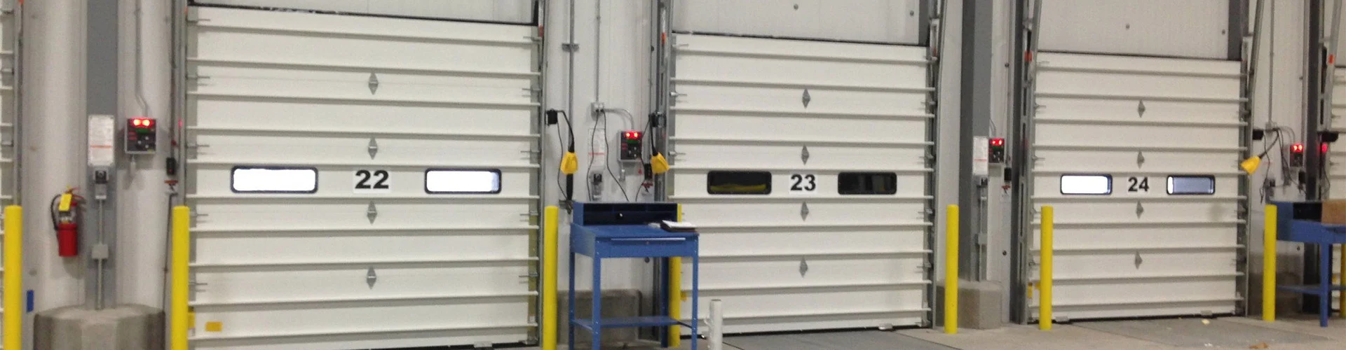
A practical movement-window review can be short but disciplined:
- Confirm the catalog identity as Pusher adjustable Plate before comparing samples.
- Measure plate thickness and verify the confirmed 4.0mm requirement.
- Place the part on a flat surface or fixture and check for visible rocking.
- Test whether the intended bolt or gauge can pass through the hole without forcing.
- Check cut edges and punched zones for burrs that could block adjustment.
- Confirm that the galvanized surface is not seriously scratched at contact areas.
- Simulate the final tightened position and observe whether adjustment travel remains usable.
- Separate cosmetic marks from functional interference, but do not ignore damaged edges.
This movement-window perspective is different from a general installation tutorial. It does not introduce unverified bolt specifications, torque values, or door types. It gives the buyer and installer a way to convert limited catalog data into a useful acceptance routine.
Factory Communication Should Start with Evidence: What Buyers Should Ask Before Ordering a Pusher Adjustable Plate
Good factory communication for a pusher plate should begin with evidence, not assumptions. The buyer should not ask only whether the supplier can provide a pusher plate. The better request is narrower: confirm the product identity as Pusher adjustable Plate, confirm the 4.0mm thickness, confirm the galvanized finish, and provide inspection evidence for appearance, edge quality, hole usability, and packing protection. This creates a practical bridge between catalog data and delivered parts.
Solution 1: Thickness and identity confirmation. Execution protocol: the supplier should match the part name to the catalog item and confirm that production samples are checked against the 4.0mm thickness requirement. The buyer can request a sample measurement photo, inspection sheet, or batch record without demanding unlisted mechanical data. Material expected behavior: consistent thickness helps reduce variation in stiffness, contact height, and bolt compression behavior during installation. Hidden cost and side-effect control: excessive documentation can slow simple orders, so buyers should request focused evidence rather than broad paperwork.
Solution 2: Edge and hole inspection. Execution protocol: after punching, cutting, or forming, the factory should check for burrs, sharp raised edges, severe distortion, and hole obstruction. The inspection should be connected to assembly usability, not only visual neatness. Material expected behavior: smoother edges reduce local stress concentration, lower the chance of zinc damage during handling, and improve bolt access. Hidden cost and side-effect control: aggressive deburring can scratch the finish if done carelessly, so the process should remove functional burrs without turning every edge into a cosmetic polishing project.
Solution 3: Galvanized finish review. Execution protocol: inspect the visible surface, edges, and contact zones for obvious peeling, rust, severe scratches, or bare areas. Since the catalog does not specify coating thickness or salt-spray hours, the buyer should avoid asking the article to prove a standard that is not listed. Material expected behavior: a sound galvanized finish gives the plate better resistance against ordinary moisture exposure than unprotected steel. Hidden cost and side-effect control: buyers should not confuse normal zinc appearance variation with failure, but visible rust or damaged coating at working edges should be treated as a functional warning.
Solution 4: Packing and handling protection. Execution protocol: the factory should prevent galvanized surfaces from grinding against one another during transport. Separators, controlled stacking, or protected packaging may be used depending on order size and shipping method. Material expected behavior: less friction during transport preserves the finish around surfaces and edges that later become installation contact zones. Hidden cost and side-effect control: overpacking raises cost and volume, so the target should be preventing damaging abrasion rather than creating luxury packaging.
| Control Variable | Practical Test Method | Expected Result | Buyer Evidence to Request |
|---|---|---|---|
| Product identity | Catalog name confirmation | Pusher adjustable Plate matched to order | Item photo or line-item confirmation |
| 厚さ | Caliper sampling | 4.0mm checked within buyer-agreed tolerance | Measurement photo or inspection record |
| Galvanized finish | Visual inspection under normal light | No obvious rust, peeling, or severe scratch | Surface sample photo |
| Hole access | Bolt or gauge pass-through | No blocking burr or distortion | Fixture or gauge check photo |
| Edge safety | Manual and visual burr review | No severe sharp raised burr | Edge close-up image |
| Packing protection | Stacking and movement review | Reduced coating abrasion during shipment | Packing photo before dispatch |
プロのヒント/チェックリスト
- Ask the supplier to confirm the exact catalog identity before discussing price.
- Request thickness verification for the 4.0mm requirement instead of accepting a verbal description.
- Check hole margins and cut edges before judging the broad galvanized face.
- Do not assume a salt-spray rating unless the supplier provides a real test report.
- Confirm that packing prevents repeated metal-to-metal rubbing during shipment.
- Use a simple fixture or bolt-pass test to validate assembly usability.
- Separate harmless zinc color variation from real coating damage, rust, or peeling.
- Keep inspection evidence tied to the order batch, not only to a generic sample.
よくある質問(FAQ)
How to change battery in garage door opener?
Changing a garage door opener battery is usually unrelated to a pusher plate. Follow the opener manufacturer’s instructions, disconnect power where required, replace the correct battery type, and test remote operation. Do not adjust door hardware at the same time unless a qualified technician confirms the mechanical system is safe.
How to adjust garage door sensors?
Garage door sensor adjustment should focus on sensor alignment, wiring, lens cleanliness, and stable mounting. A pusher plate is a separate metal hardware component and should not be treated as part of the photo-eye sensor system. If the door reverses unexpectedly, inspect both the sensor alignment and mechanical movement path.
How do you program a garage door opener?
Programming a garage door opener depends on the opener brand and control board. Use the manufacturer’s learn-button sequence or remote setup procedure. A pusher adjustable plate does not control opener programming, but poor mechanical alignment in door hardware can still affect how smoothly the opener operates after programming.
What should buyers verify before ordering a Pusher adjustable Plate?
Buyers should verify the product name, 4.0mm thickness, galvanized finish, visible edge condition, hole usability, and packing protection. The catalog does not provide steel grade, coating thickness, hole dimensions, or load rating, so those details should not be assumed unless the supplier provides separate evidence.
Why can a galvanized pusher plate still show rust near edges?
Rust may begin near cut, punched, bent, or abraded areas because those zones experience more mechanical contact and possible coating damage. The broad face may still look acceptable while the working edge shows early exposure. This is why edge-path inspection is more useful than surface-only review.
 English
  Русский
  日本語
日本語  한국어
한국어  Français
  Deutsch
  العربية
  Português
  Español