Shaft Coupler Case Study for Garage Doors
Reference Standard: Relevant material and performance testing standards may include ISO 2768 for general dimensional tolerances, ASTM B117 for neutral salt spray exposure when galvanized finish corrosion resistance must be evaluated, and ASTM E18 or ASTM E384 when a buyer separately requests verified hardness data. These standards are reference directions only; the catalog data for this coupler series does not publish certified test results.
Short Answer
When a Coupler Becomes a Hidden Shaft Memory Point
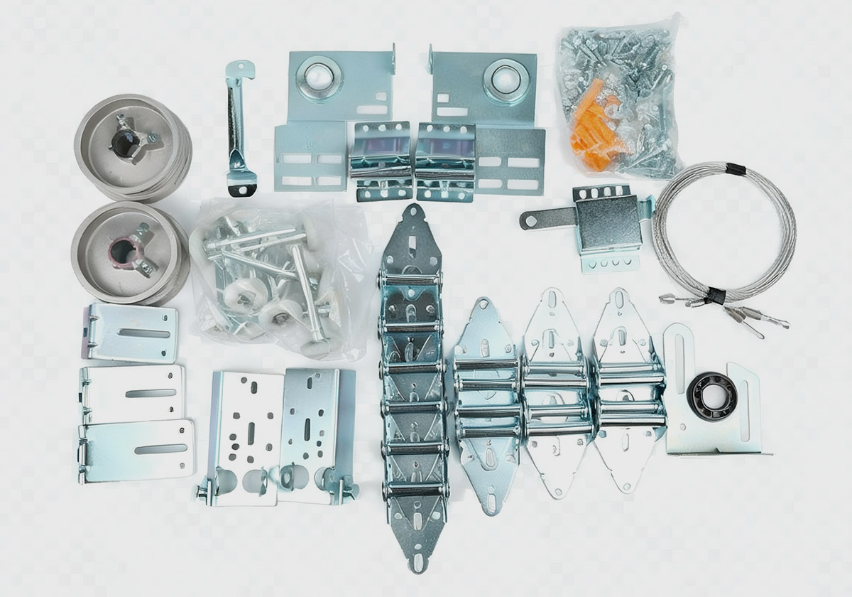
A set screw shaft coupler is often described as a small accessory, but its real behavior is closer to a hidden mechanical memory point inside the door shaft system. The coupler does not carry the full door load by itself, and it should not be sold as though it replaces the spring, drum, track, hinge, or shaft. Its function is narrower and more technical: it joins shaft sections, keeps the shaft route continuous, and receives repeated traces of torsional transfer, clamping pressure, alignment error, vibration, and local surface contact.
The catalog records six shaft coupler routes in the Shaft & Stick Series: BT-SH605, BT-SH606, BT-SH607, BT-SH608, BT-SH609そして BT-SH610. The recorded inside diameter routes are 1インチ そして 1-1/4 inch. The recorded body length routes are 90mm そして 120mm. The material or surface routes include aluminum そして galvanized options. Those numbers are not decorative product copy; they are the only hard boundary that should control the article’s specification language.
The “memory point” idea is useful because a coupler records the history of the shaft’s working condition through contact marks, bore pressure, screw pressure, and small alignment deviations. If a shaft connection is slightly misaligned during assembly, the coupler does not announce that error immediately. Instead, the bore wall and shaft surface begin to share uneven contact. During the early stage, the system may still look functional. In the middle stage, vibration and repeated door movement can make the contact pattern more visible. In an extreme stage, the user may notice movement noise, shaft position inconsistency, or a need to retighten fastening points. These are not certified failure stages from the catalog; they are objective mechanical progression models based on contact pressure and repeated cyclic movement.
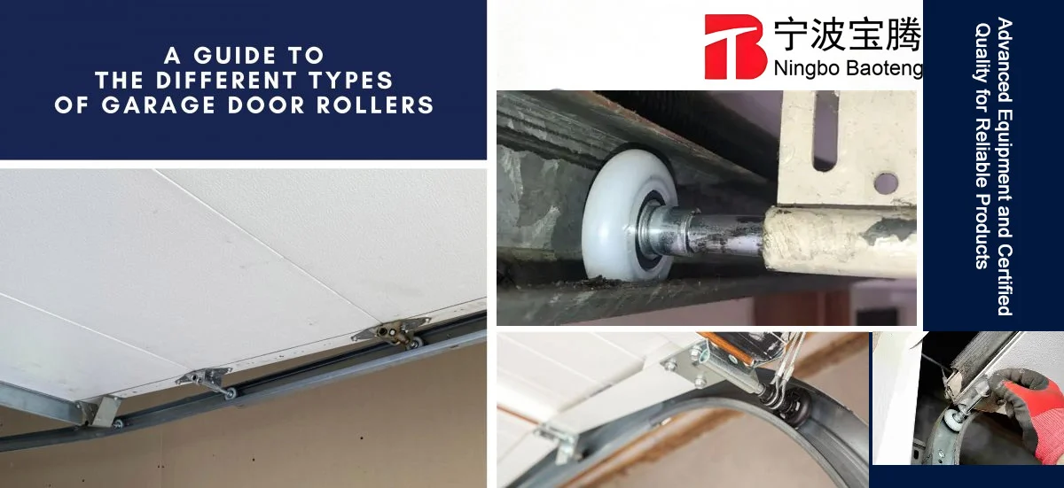
A cross-dimensional comparison helps separate a coupler from other garage door hardware. A roller mainly responds to rolling friction inside the track. A hinge mainly responds to panel articulation and screw-holding stability. A shaft coupler responds to internal shaft continuity and localized compression between the bore and shaft surface. That means a coupler problem may not look like a track problem, a roller problem, or a panel problem. Its symptom pattern is more likely to appear as connection movement, uneven rotation feel, or a difference between shaft sections.
An edge-case model is useful for procurement: imagine a covered garage environment with dust, occasional humidity, and repeated door operation. The 1インチ coupler route is installed on a matching shaft, but the surface has minor debris during assembly. At first, the debris only changes contact feel. After repeated cycles, the contact area can create localized pressure marks. If the coupler is aluminum, excessive tightening can mark the bore more easily than a harder steel surface would. If the route is galvanized, a scratched coating area can become more vulnerable to oxidation at exposed points. The product page should not dramatize this into a guaranteed failure claim, but it should teach buyers that the coupler is a contact-sensitive component rather than a simple sleeve.
For SEO, this angle also creates real information gain. Many pages discuss replacement, size selection, or general repair. This case study instead treats the coupler as a small physical archive of shaft behavior, using only the recorded model range, bore routes, length routes, and material or finish routes as the data anchor.
Set Screw Shaft Coupler Contact Pressure Case Study
A set screw shaft coupler depends on compression logic. The shaft surface, bore wall, and set screw direction create the practical connection. The catalog does not publish screw-hole diameter, compatible screw length, installed screw seating depth, tightening torque, or tested slip resistance. That absence matters. Without those details, the safest technical content should focus on contact quality, bore matching, body length selection, and inspection boundaries rather than claims of heavy-duty performance.
The verified geometry gives two main bore routes: 1インチ そして 1-1/4 inch. A bore that is too large reduces stable contact because the shaft can sit with more clearance inside the coupler. A bore that is too tight may create assembly difficulty or surface damage if forced. Even when the nominal bore is correct, actual shaft condition matters. Burrs, plating buildup, surface dents, or debris can change how the bore wall touches the shaft. In a garage door shaft connection, the coupler works best when the shaft enters straight, the bore wall receives contact evenly, and the clamping force does not concentrate into one damaging point.
The recorded length routes, 90mm そして 120mm, affect the engagement zone. A longer coupler body can provide more axial coverage, but the catalog does not prove a higher torque rating simply because a part is longer. A shorter route may be enough for some shaft connection layouts, while a longer route may be preferred when the buyer wants more engagement surface. The accurate statement is not “120mm is stronger.” The accurate statement is that 90mm and 120mm are different body length routes, and the final suitability depends on shaft condition, installation geometry, screw arrangement, and application requirements.
A useful comparison test case can be described without inventing numbers. Take two couplers with the same nominal bore, one installed on a clean matching shaft and one installed on a shaft with surface contamination. Under repeated opening cycles, the clean assembly is expected to maintain more uniform contact because the bore wall and shaft surface can seat evenly. The contaminated assembly may develop uneven pressure points, making the contact pattern less stable. This is a physics-based comparison, not a catalog-certified endurance result.
| Contact Variable | Expected Mechanical Effect | Safe Content Boundary | Data Status |
|---|---|---|---|
| 1 inch bore route | Matches shaft systems designed around 1 inch connection points | Can be stated as a catalog route | Verified in catalog |
| 1-1/4 inch bore route | Supports larger bore matching where specified | Can be stated as a catalog route | Verified in catalog |
| 90mm body length | Provides one recorded engagement-length route | Cannot be called higher or lower strength without testing | Verified in catalog |
| 120mm body length | Provides another recorded engagement-length route | Cannot be treated as certified load improvement | Verified in catalog |
| Clean shaft surface | Supports more stable contact seating | Can be recommended as inspection logic | Engineering common sense |
| Unknown screw geometry | Limits claims about seating depth or tightening behavior | Must remain unpromised before drawings | Missing from catalog |
The edge extreme scenario here is not a dramatic failure story; it is a progressive contact-loss model. In the initial stage, a slightly mismatched shaft or uneven screw pressure may only create minor local marks. In the middle stage, repeated torsional movement can enlarge the practical contact zone on one side while leaving the opposite side less engaged. In the limit stage, the coupler may require rechecking because the shaft surface no longer shares pressure evenly with the bore. This model should be used to explain why bore inspection, shaft-fit trial assembly, and thread engagement checks are necessary.
KEY TAKEAWAYS
- Uneven bore-to-shaft contact can appear before any visible shaft separation.
- Repeated door cycles can expose weak seating that was hidden during first installation.
- Surface marks around the bore or shaft end may indicate concentrated compression rather than uniform engagement.
A buyer reviewing garage door hardware product coverage should not treat every shaft coupler as interchangeable just because the product name sounds similar. The inner diameter, body length, material route, surface condition, and actual shaft preparation all shape the connection result.
Aluminum and Galvanized Routes Without Performance Overclaiming
The catalog confirms both aluminum そして galvanized routes, but it does not publish tensile strength, yield strength, coating thickness, salt spray hours, torque test results, or certified corrosion class. This distinction is important because material names are often misread as performance certificates. In a careful product page, “aluminum” should mean an aluminum route recorded for specific coupler items, and “galvanized” should mean a galvanized finish route recorded for specific coupler items. Neither term should be stretched into a broad promise.
Aluminum is generally valued for lower density and natural oxide behavior. In a shaft coupler, this can be useful where weight and ordinary indoor corrosion behavior matter. Yet aluminum is also softer than many steel routes, so excessive localized screw pressure can create impressions or bore deformation. That does not make aluminum unsuitable; it means installation pressure must be managed and verified by fit trial, surface inspection, and proper fastening practice. The catalog states aluminum for BT-SH605 と 1 inch inside diameter and 90mm lengthそして BT-SH607 と 1 inch inside diameter and 120mm length. Those are product facts, not strength rankings.
A galvanized route uses a zinc-based surface protection concept. Zinc can help resist ordinary oxidation before the coating is damaged. Yet galvanized protection is still surface-dependent. If a galvanized coupler is scratched during handling, forced assembly, or poor storage, exposed base material can become more vulnerable. The catalog records galvanized routes for BT-SH606, BT-SH608, BT-SH609そして BT-SH610, including 1インチ, 1 inch and 1-1/4 inchそして 1-1/4 inch inside diameter routes. The recorded body length routes include 90mm そして 120mm.
The cross-dimensional comparison here is material naming versus evidence naming. A material name answers “what route is recorded.” A certificate answers “what performance has been tested.” A product page can safely say that a coupler is aluminum or galvanized when the catalog records it. It cannot safely say certified anti-corrosion, tested load capacity, or high-cycle anti-slip performance unless actual testing documents support those claims. This is especially important for B2B SEO because technically aware buyers often notice when copy turns material vocabulary into unsupported performance language.
An edge extreme model can be built around scratched surfaces. In a covered garage environment with occasional humidity, a galvanized surface that remains intact is expected to resist ordinary oxidation better than exposed steel. If the surface is scratched near a contact zone, oxidation risk becomes more local. For an aluminum coupler, the issue is not zinc-layer loss but potential bore marking under excessive point pressure. In both routes, the same conclusion applies: the material route influences inspection focus, but it does not replace fit verification.
What the Product Page Should Refuse to Promise Before Drawings Arrive
A credible case study for garage door couplings should include a refusal list. This is not weakness; it is evidence discipline. The available catalog data is useful, but it does not include everything required for a full engineering claim. Before supplier drawings, screw samples, thread gauge records, and mounted cross-section photos are available, the product page should refuse to promise screw-hole diameter, compatible screw length, installed screw seating depth, exact torque capacity, cycle lifeそして certified anti-slip rating.
The safe writing boundary is still strong. The page can state the model range from BT-SH605 to BT-SH610. It can state the bore routes of 1インチ そして 1-1/4 inch. It can state the length routes of 90mm そして 120mm. It can state the aluminum and galvanized routes where recorded. It can explain suitability for covered garage or industrial door shaft connection environments with repeated movement, vibration, dust, and occasional humidity. It can recommend objective inspection: incoming material check, bore diameter inspection, overall length inspection, visual finish inspection, thread or set-screw engagement inspection, shaft-fit trial assembly, and batch-level packaging inspection.
Four factory-level acceptance controls should shape this type of page.
1. Bore-to-shaft fit control. Execution protocol: inspect the coupler bore against the matching shaft size before assembly, especially for the 1インチ そして 1-1/4 inch routes. The check should confirm that the shaft enters without forcing and without excessive clearance. Material expectation: stable contact should reduce localized movement and help the coupler seat more evenly. Hidden cost control: a buyer should avoid accepting parts based only on catalog naming, because nominal size does not replace actual fit checking.
2. Body length verification. Execution protocol: separate 90mm そして 120mm routes during incoming inspection and carton labeling. Material expectation: the correct length route helps maintain the intended engagement zone. Hidden cost control: do not claim that one length is universally stronger. Treat length as a specification match, not a guaranteed load upgrade.
3. Surface route inspection. Execution protocol: inspect aluminum routes for bore marks, handling damage, and visible deformation; inspect galvanized routes for coating continuity, exposed scratches, and storage corrosion. Material expectation: each surface route has a different risk focus. Hidden cost control: avoid mixing corrosion language with certified salt spray claims unless ASTM B117 or equivalent records exist.
4. Set-screw engagement boundary. Execution protocol: confirm that the threaded area accepts the intended fastener smoothly, but do not publish screw dimensions until drawings and samples support the data. Material expectation: smoother thread engagement can reduce assembly uncertainty. Hidden cost control: publishing unverified screw size may create returns, installation disputes, and technical credibility loss.
| Acceptance Item | Inspection Method | Common Risk Prevented | Claim Boundary |
|---|---|---|---|
| Bore diameter | Gauge or shaft-fit trial | Loose seating or forced assembly | Size route only unless tolerances are provided |
| Body length | Caliper or length fixture | Wrong engagement route | State 90mm or 120mm only |
| Aluminum body | Visual and fit inspection | Bore marking from over-tightening | Do not claim certified strength |
| Galvanized finish | Visual finish inspection | Scratched zinc layer and local oxidation | Do not claim salt spray hours without reports |
| Thread engagement | Trial fastening check | Poor screw seating or thread damage | Do not publish screw size without drawings |
| Packing separation | Model and label audit | Mixed models in bulk order | State batch control logic, not certified traceability |
PRO-TIP / CHECKLIST
- Confirm whether the shaft route is 1インチ または 1-1/4 inch before discussing coupler selection.
- Separate 90mm そして 120mm body length routes during warehouse and carton checks.
- Inspect aluminum couplers for bore marks before assembly.
- Inspect galvanized couplers for coating scratches and storage oxidation.
- Run a simple shaft-fit trial before bulk shipment approval.
- Do not publish screw-hole diameter, screw length, or seating depth without drawings.
- Avoid using “tested anti-slip” or “rated torque” language unless actual reports are supplied.
- Keep model numbers visible in quotation sheets to reduce mixed-route selection errors.
The most useful product page is not the one that promises the most. It is the one that makes the evidence boundary visible while still helping the buyer understand what the catalog proves. For a garage door shaft coupler, the real SEO advantage comes from disciplined technical writing: measured data where available, physical logic where data is missing, and no invented proof.
よくある質問(FAQ)
How to install a garage door shaft coupler?
Match the coupler bore to the shaft route, such as 1インチ または 1-1/4 inch, then confirm shaft insertion and contact before fastening. The catalog does not provide screw size or torque data, so final installation should follow supplier drawings or a qualified door hardware technician’s instructions.
How to reengage a garage door after shaft movement?
First identify whether the issue comes from the opener, spring system, cable drum, shaft, or coupler. A coupler can affect shaft continuity, but it is not the only possible cause. Do not loosen or adjust spring-loaded parts without trained support, because garage door systems can store dangerous mechanical energy.
Where to purchase garage door springs and related couplers?
Garage door springs and couplers should be sourced by matching system type, shaft size, door weight requirements, and hardware layout. For couplers, the verified catalog routes here include BT-SH605 to BT-SH610, 1 inch and 1-1/4 inch boresそして 90mm or 120mm body lengths.
How to reset a LiftMaster garage door opener if the coupler was replaced?
Resetting the opener is separate from validating the shaft connection. After any shaft coupler replacement, confirm that the shaft connection is mechanically seated and that the door moves correctly before opener adjustment. Follow the opener manufacturer’s official reset procedure and avoid using the opener to force a misaligned door.