
Center Bearing Support Bracket Deep Dive
Reference Standard: Relevant material and performance testing standards, including dimensional inspection practices for formed metal hardware and zinc-coated steel concepts aligned with ASTM A653/A653M and general corrosion terminology from ISO.
Short Answer
A center bearing support bracket sits in a difficult mechanical position. It is close to torsion spring behavior, shaft rotation, wall-side fastening pressure, and repeated door movement. That means the bracket does not fail only when steel breaks. It can create trouble much earlier, when a small wall-side shift changes the bearing seat angle, when a galvanized edge is damaged during handling, or when a plate that looks flat enough under visual inspection begins to translate vibration into the torsion shaft.
The related catalog data does not list an exact item named “garage door center bearing support bracket.” It does, though, list closely related bracket hardware: residential bearing brackets with 2.5mm and 4.0mm thickness, 85mm bearing center distance, e galvanized finish; left and right bearing brackets with 2.5mm thickness, 85mm bearing center distance, and galvanized finish; industrial bearing brackets with 4.0mm thickness and center distances of 85mm, 110mm, 123mm, 148mm, and 185mm; a spring center bracket with 2.5mm thickness and galvanized finish; and a support bracket with 4.0mm thickness and galvanized finish. Those values create a practical engineering boundary for discussing how a center support bracket should be selected, inspected, and validated.
For procurement teams comparing sectional garage door hardware, the most useful question is not whether the bracket is “heavy duty.” The better question is whether the bracket can keep the bearing seat, wall contact plane, and rotating shaft relationship stable after many open-close cycles. This article uses that risk-control angle and links it with practical inspection logic, material behavior, and factory-level acceptance checkpoints. For broader product context, see Baoteng garage door hardware resources.
When the Center Support Bracket Becomes a Vibration Translator, Not Just a Bearing Holder
A center bearing support bracket is often described as a stationary part. That description is mechanically incomplete. The bracket may not rotate, but it receives vibration from rotating and moving systems around it. The torsion shaft rotates. The spring system changes stored energy during door travel. The door panels create repeated movement. The wall or header behind the bracket receives fastening pressure. The bracket becomes the bridge between these different mechanical behaviors.
The catalog-related bracket system provides three useful boundaries for this discussion: 2.5mm plate thickness, 4.0mm plate thickness, e galvanized finish. These are not decorative details. Thickness influences how the plate resists bending and local deformation around holes. A galvanized surface helps protect the steel substrate against ordinary humid garage conditions, but it does not turn the bracket into a maintenance-free component. If the zinc layer is scratched at an edge, or if the bracket is forced against an uneven wall surface, the protection and mechanical contact quality can decline at different speeds.
A useful extreme scenario model is a high-cycle sectional door installed in a semi-enclosed garage where temperature changes, humidity, and vibration are all present. In the early stage, a properly seated 2.5mm galvanized spring center bracket may appear stable, especially if the wall surface is flat and fasteners are tightened evenly. In the middle stage, repeated door movement can reveal wall-side compression marks, light fretting around the mounting interface, or a small change in perceived operating noise. In the limit stage, the problem may no longer be visible as one dramatic defect. Instead, the bracket may transmit more vibration into the wall, while the bearing seat begins to work under slightly less favorable alignment.
A cross-dimensional comparison makes this clearer. Compare a 2.5mm galvanized bracket mounted on a dense, flat substrate with a 4.0mm galvanized support bracket mounted on a softer or uneven surface. The thicker part may have greater plate stiffness, but the installation surface can still dominate the vibration path. The thinner part may behave better when the wall contact is clean, flat, and evenly compressed. This does not mean thinner is better. It means thickness, fastening, wall hardness, and shaft behavior must be read as a system.
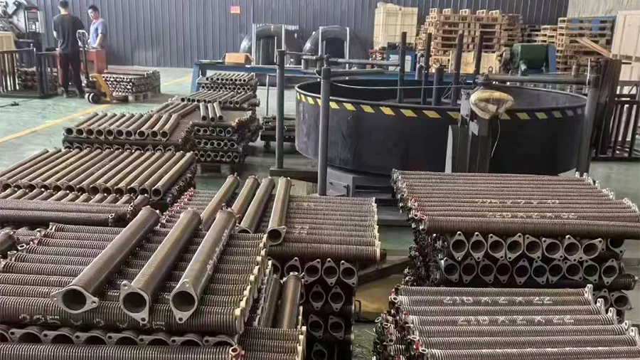
KEY TAKEAWAYS
- A bracket can look intact while already transferring abnormal vibration into the wall-side mounting surface.
- Uneven fastening pressure can make a flat bracket behave like a tilted bearing support.
- Galvanized finish protects the steel surface, but scratched edges and compressed contact zones still need inspection.
The Hidden Contact Map Between Bearing Seat, Plate Plane, and Wall Surface
The most important surface on a center bearing support bracket is not always the visible front face. The hidden contact map matters more. This map includes the bearing seat, the plate plane, the wall-side mounting surface, the edges around punched holes, and any formed bend that controls stiffness. If these areas do not work together, the bracket can transfer load unevenly even when the nominal thickness and finish appear correct.
The catalog data gives several useful references. Related bearing brackets include 85mm bearing center distance for residential applications, while industrial bearing brackets show center distances of 85mm, 110mm, 123mm, 148mm, and 185mm. These dimensions are not interchangeable decorative options. They represent the geometry through which the shaft, bearing, bracket body, and mounting system meet. A center support bracket that works near a spring and shaft assembly must hold its reference position without creating an angular error at the bearing seat.
The micro-mechanism is simple but important. Steel plate stiffness increases with thickness, so a 4.0mm galvanized support bracket generally has more resistance to bending than a 2.5mm bracket of similar geometry. Yet the wall-side surface can change the real behavior. If the wall is uneven, the plate may contact the substrate at a few high points instead of across a broad surface. Fastener tightening can then pull the bracket into a slightly stressed plane. Around the bearing area, that stress can translate into uneven seating pressure. The bearing may still fit, but the shaft may no longer behave as if the support is fully square.
A practical edge-case model is a bracket installed after storage, transport, and site handling. At first, the galvanized finish and hole layout may pass a simple visual check. During installation, a small burr around a hole or a slight packaging bend may prevent the plate from sitting flush. After door cycles begin, the bearing seat may experience repeated micro-load variation. At the extreme boundary, the bracket does not need to crack to become a problem. It only needs to shift the bearing’s working plane enough to create uneven rotation feel, localized noise, or fastener-side stress marks.
A comparison test can be framed without inventing load numbers. Place two galvanized brackets of the same nominal type on a flat reference surface. One has clean hole edges and an even wall-side plane. The other has a small burr and a slightly distorted edge. Under visual review, both may look acceptable at a distance. Under contact review, the second bracket shows a more concentrated support pattern. In real use, that contact pattern can become the starting point for vibration concentration and inconsistent seating.
| Inspection Zone | Relevant Catalog Boundary | What to Check | Risk If Ignored |
|---|---|---|---|
| Bearing seat area | 85mm or industrial center-distance family | Seat alignment and circular contact | Shaft-side instability |
| Plate plane | 2.5mm or 4.0mm thickness | Flatness against reference surface | Tilted bracket behavior |
| Mounting holes | Formed metal bracket hardware | Hole position and edge condition | Uneven fastener pressure |
| Galvanized surface | Galvanized finish | No severe peeling, red rust, or exposed damage | Local corrosion path |
| Packaging condition | Finished bracket hardware | No compression bend or edge distortion | Poor wall-side contact |
Why Small Wall-Side Movement Can Become Shaft-Side Instability After Repeated Door Cycles
Small movement is dangerous because the bracket works as a geometric reference. A center bearing support bracket is not only a static plate attached to a wall. It is part of a chain: wall surface, fastener preload, bracket plane, bearing seat, torsion shaft, spring behavior, and door travel. A tiny change at the wall-side interface can become a visible operational difference at the shaft-side interface.
Start with the wall-side fastening point. If fastener pressure is not distributed evenly, one side of the bracket may be compressed more heavily than the other. With a 2.5mm galvanized bracket, the plate may be more sensitive to local pressure concentration than a thicker plate of similar geometry. With a 4.0mm galvanized support bracket, the plate may resist bending better, but if the wall surface is uneven or the hole position is forced, the stress can still transfer into the system. The thickness helps, but it does not cancel poor contact geometry.
During the early cycle period, the bracket may only show slight acoustic variation. The door may still open and close, and the shaft may still rotate. During the middle period, repeated vibration can make fastener seating marks more visible. The bracket may settle into a slightly altered plane. During the limit period, the bearing can continue to operate, but the shaft-side stability becomes less predictable because the bracket reference is no longer as clean as it was during installation.
This is where the 85mm residential bearing center distance e o 85/110/123/148/185mm industrial center-distance range should be treated as geometry references, not just catalog values. A bracket with the correct center distance can still create trouble if the mounting plane changes after repeated cycles. Correct nominal geometry is the first gate. Stable installed geometry is the second gate.
A cross-system comparison is useful. In a low-cycle residential setting, a small wall-side movement may stay unnoticed for a long time because the operating frequency is lower. In a higher-cycle commercial or industrial setting, the same kind of micro-movement may become visible sooner as noise, fastener witness marks, or a less smooth shaft feel. The material has not changed its identity; the environment has changed the speed at which small geometric errors become operational symptoms.
The safest procurement interpretation is to avoid treating the bracket as a single isolated SKU. It should be validated together with wall-side contact, shaft position, bearing seat alignment, thickness category, galvanized finish condition, and expected duty environment. This is especially important when switching between residential and industrial assemblies, because the industrial center-distance family is wider and the bracket may carry different installation assumptions.
Factory-Level Reading: Separate Cosmetic Galvanizing Marks from Real Assembly Risk
Factory inspection for this product category should not turn every surface mark into a rejection. A galvanized metal bracket can show ordinary surface variation from forming, handling, or storage. The critical task is to separate cosmetic marks from assembly risks. Since the catalog does not provide a dedicated quality-control process for the exact product name, the following approach should be treated as general objective inspection logic for galvanized garage door bracket hardware, not as a claimed proprietary factory standard.
Solution 1: Dimensional gate for thickness and center-distance control.
Execution Protocol: Inspect the incoming or finished bracket against the relevant thickness family, especially 2,5 mm e 4,0 mm, and confirm the applicable bearing center distance such as 85 mm for residential bearing bracket logic or the industrial family of 85mm, 110mm, 123mm, 148mm, and 185mm where relevant. The inspector should check the plate, bearing seat, mounting hole pattern, and any width-related requirement before packaging approval.
Expected Material Evolution: Correct dimensional control reduces the chance that the plate will be forced into a stressed position during assembly. The steel does not become stronger after inspection, but the risk of installing a geometrically incompatible bracket is reduced.
Hidden Cost and Side-Effect Avoidance: Over-inspection can slow production if every cosmetic mark is treated as structural failure. The better approach is to separate dimensional nonconformity from harmless surface variation.
Solution 2: Wall-plane and plate-flatness verification.
Execution Protocol: Place the bracket against a flat reference surface and look for rocking, corner lift, or localized contact. Pay attention to formed edges and hole areas because punched and bent features can create subtle distortion.
Expected Material Evolution: A bracket that sits flatter at installation is less likely to develop uneven fastener pressure. The material response remains more predictable because the plate is not preloaded into an unintended shape.
Hidden Cost and Side-Effect Avoidance: Excessive correction after forming can damage the galvanized surface. The process should focus on prevention through consistent forming, handling, and packaging.
Solution 3: Galvanized finish risk classification.
Execution Protocol: Separate minor color variation from serious issues such as wide peeling, exposed steel, red rust, deep scratches at bearing contact areas, or damage around mounting holes. Inspect edges because cut or punched zones often reveal the first weak points in coating continuity.
Expected Material Evolution: A sound galvanized surface slows ordinary corrosion of the steel substrate in humid garage environments. Damaged areas may become local corrosion starting points, especially when combined with trapped moisture and contact pressure.
Hidden Cost and Side-Effect Avoidance: A strict visual-only rule can create unnecessary rejection. The inspection should prioritize functional zones: bearing seat area, mounting holes, wall-side contact plane, and edges exposed to handling abrasion.
Solution 4: Assembly-fit sampling before batch release.
Execution Protocol: Use sample-fit verification to confirm that the bracket can be mounted without forcing the bearing seat, holes, or support plane into misalignment. Check whether the shaft-facing area remains square enough for stable rotation logic.
Expected Material Evolution: Proper fit avoids hidden stress concentration. The bracket begins service without unnecessary bending memory, and the bearing interface is less likely to develop uneven pressure.
Hidden Cost and Side-Effect Avoidance: Sampling cannot replace dimensional control. It should support measurement, not act as the only quality gate.
PRO-TIP / CHECKLIST
- Confirm whether the application is closer to residential bearing bracket behavior or industrial bearing bracket behavior.
- Verify the correct thickness family before reviewing surface finish.
- Check the bearing center distance before approving a mounting layout.
- Inspect wall-side flatness instead of judging only the front face.
- Treat red rust, exposed steel, and severe peeling as functional risks, not cosmetic details.
- Review punched-hole edges for burrs, distortion, or compression marks.
- Confirm packaging has not bent the bracket before shipment or installation.
- Use sample fitting when the bracket works near a torsion shaft or spring center support.
| Factory Checkpoint | Practical Test Method | Acceptance Logic | Risk-Control Purpose |
|---|---|---|---|
| Thickness family | Caliper or gauge inspection | Match 2.5mm or 4.0mm category where specified | Prevent stiffness mismatch |
| Bearing center distance | Dimensional measurement | Confirm 85mm or relevant industrial distance | Prevent shaft-position error |
| Plate plane | Flat reference contact check | No obvious rocking or forced seating | Reduce wall-side preload imbalance |
| Galvanized surface | Visual and touch inspection | No severe peeling, red rust, or exposed functional damage | Limit corrosion initiation |
| Hole condition | Hole edge review | No severe burr or deformation near mounting points | Improve fastener seating |
| Assembly fit | Sample mounting simulation | Bearing seat and plate remain aligned | Reduce hidden installation stress |
Perguntas frequentes (FAQ)
How to program a Linear garage door remote?
Programming a Linear remote is usually an opener-control procedure, not a bracket procedure. Follow the opener manufacturer’s learn-button steps and confirm door travel is smooth before programming. If the torsion shaft or center support area is unstable, fix the mechanical issue before remote setup.
How to connect a garage door remote?
A remote connects to the opener receiver, while the center bearing support bracket affects mechanical shaft stability. Program the remote only after the door opens and closes without binding, unusual vibration, or abnormal shaft movement near the spring support area.
How do I program my Craftsman garage door opener?
Use the Craftsman opener’s learn button and remote instructions for pairing. Before pairing, inspect whether the garage door hardware moves smoothly. A misaligned bearing support bracket can increase resistance, which may make opener calibration or travel behavior feel inconsistent.
How to set a LiftMaster garage door opener?
Set travel limits and force settings according to LiftMaster instructions, then test reversal and smooth operation. Mechanical hardware should be checked first. A center bearing support bracket with poor wall contact or shaft alignment can affect opener load perception.
How to program a Lexus garage door opener?
A Lexus HomeLink-style system usually pairs with the opener remote or receiver. Pairing does not correct mechanical issues. If the garage door hesitates, vibrates, or sounds uneven near the torsion shaft, inspect support brackets before blaming the vehicle transmitter.
How to open a garage door when power is out?
Use the manual release only when the door is fully closed, unless the opener manual says otherwise. If the spring shaft or center support bracket area looks unstable, avoid forcing the door. A bracket-related alignment problem can make manual movement harder and less predictable.
 English
  Русский
  日本語
日本語  한국어
한국어  Français
  Deutsch
  العربية
  Português
  Español