
Garage Door Bearing Bracket Specification Guide
Reference Standard: Relevant material and performance testing standards, including ASTM E8/E8M for metallic tensile behavior and ISO 1461 as a general reference for zinc-coated steel protection where applicable to galvanized hardware.
Short Answer
A garage door bearing bracket works inside a high-cycle mechanical system where the door, shaft, spring torque, bearing, wall fasteners, and track frame interact during every opening and closing event. The cataloged bracket range includes residential bearing brackets with 85mm bearing center distance, and industrial bearing brackets with multiple bearing center distances of 85mm, 110mm, 123mm, 148mm, and 185mm. It also shows galvanized bearing bracket formats in 2.5mm, 2.5 & 4mm, and 4.0mm thickness categories.
This means the bracket should be evaluated as a geometric and structural interface, not as a flat commodity plate. A mismatch in center distance can shift the reaction force away from the intended support line. A mismatch in thickness can change the stiffness boundary between the bearing and the mounting surface. A damaged galvanized layer can reduce surface protection at contact areas where condensation, vibration, and fastener pressure are present.
For broader sectional door hardware sourcing context, see the related sectional garage door hardware supplier overview.
When the Bearing Center Becomes the Hidden Load Map of a Garage Door
Bearing center distance is the first hidden design variable in a garage door bearing bracket. The product data identifies residential bearing bracket options with 85mm bearing centre / center distance, while industrial bearing bracket options show a wider set of 85mm, 110mm, 123mm, 148mm, and 185mm center distances. These numbers are not decorative measurements. They describe where the bearing axis sits relative to the bracket mounting plane, and that position determines how the shaft load is transferred into the wall, end plate, or supporting door hardware frame.
In a sectional garage door system, the torsion shaft is not perfectly isolated. It receives spring torque, carries rotating components, and reacts to door movement through the cable drum and bearing support structure. When the bearing center distance is too short for the actual hardware geometry, the shaft may sit too close to the mounting plane, increasing local contact stress around the bearing pocket or fastener region. When the center distance is too long for the system, the shaft support line can create a larger moment arm, increasing bending demand on the bracket plate and mounting fasteners. The bracket is therefore a load-map component, not just a support accessory.
A useful extreme scenario model is a high-cycle industrial door operating in humid air with repeated daily movement and intermittent vibration from the door track. During the early stage, an incorrectly selected center distance may not create obvious failure. The door still opens, the shaft still rotates, and the bracket looks visually acceptable. During the mid-stage, small alignment errors can become visible as shaft drag, uneven bearing contact, or slight bracket face movement under load. At the limit stage, the accumulated reaction force may concentrate around the bearing seat or fastener area, causing loss of stable alignment. This model does not require invented test values; it follows the mechanical logic of repeated torque, radial bearing load, and mounting-plane reaction.
A cross-dimensional comparison test can be framed as two assemblies: one using an 85mm residential bearing bracket in a residential hardware layout, and another using an industrial bracket selected from 85mm, 110mm, 123mm, 148mm, or 185mm center distance options. The residential assembly should be evaluated for compact alignment and stable fit at the standard bearing center position. The industrial assembly should be evaluated for whether the selected center distance matches the shaft height, bearing support line, and hardware frame geometry. The important question is not whether a larger bracket looks stronger, but whether the bearing axis is placed where the door system expects it to be.
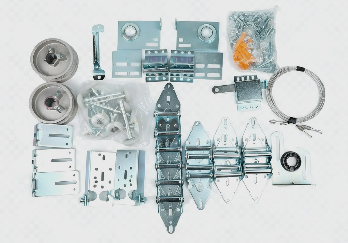
The secondary system risk is that a center-distance error can be misread as a bearing quality issue. If the bearing is forced to operate with side loading caused by incorrect bracket geometry, the resulting drag may appear to come from the bearing itself. In reality, the bracket may be creating an offset load path. This is why bearing center distance should be confirmed before diagnosing shaft noise, roller drag, or opener force irregularity. A bearing can only perform correctly when the bracket places it in the correct mechanical position.
Garage Door Bearing Bracket Thickness and Stiffness Boundary
A garage door bearing bracket should not be selected by appearance alone because thickness changes the stiffness boundary of the bearing support. The documented range includes 2.5mm residential bearing bracket formats, 2.5 & 4mm residential bearing bracket formats, and several 4.0mm bearing bracket / industrial bearing bracket formats. The relevant interpretation is not “thicker is always better.” The better interpretation is that each thickness range belongs to a different load expectation, installation geometry, and deformation tolerance.
A 2.5mm residential bearing bracket can be suitable where the door size, shaft load, and duty cycle are consistent with residential operation. A 4.0mm industrial bearing bracket creates a stiffer plate boundary that can better resist bending under heavier shaft reaction forces. The mixed 2.5 & 4mm category indicates that some residential bracket designs may use different thickness zones or product formats depending on the load-bearing role. The key is to match thickness to the operating system instead of treating all bearing brackets as interchangeable.
Mechanically, plate thickness affects flexural rigidity in a nonlinear way. When the bracket face experiences a bending moment from shaft reaction or mounting-plane offset, a thinner plate reaches measurable deflection sooner than a thicker plate under comparable loading. In practical terms, a 2.5mm bracket may remain stable in a residential system but may not provide the same stiffness reserve in a heavier industrial door layout. A 4.0mm bracket may be appropriate where the bearing center distance is larger, the shaft reaction is stronger, or the door experiences higher operating cycles.
A practical edge-case fatigue model can be described in three phases. In the initial phase, both 2.5mm and 4.0mm brackets may hold alignment during normal movement. The difference is not always visible during early installation. In the middle phase, repeated torsion and radial load can reveal the stiffness gap: the thinner bracket may show slightly more face movement, while the thicker bracket retains more alignment stability. In the limit phase, if the bracket is underspecified for the application, small elastic movement can become a permanent geometry change around the bearing seat or fastener zone.
A cross-dimensional test case would compare two brackets under the same shaft-support layout: one 2.5mm residential bearing bracket and one 4.0mm industrial bearing bracket. The inspection focus should include bearing axis stability, mounting face flatness, fastener seating, and whether the shaft rotates without side pressure after repeated movement cycles. This does not require a claim of a universal load rating. It simply recognizes that thickness affects stiffness, and stiffness affects bearing alignment over time.
The hidden secondary effect is installer overcorrection. When a bracket feels flexible or alignment is slightly off, installers may compensate by tightening fasteners harder. Extra tightening can improve short-term contact but may also concentrate pressure around holes, distort the mounting face, or scratch the galvanized surface. In this way, thickness mismatch can lead to surface wear and fit problems even before a visible bracket failure occurs.
KEY TAKEAWAYS
- A bracket that matches the bearing but not the shaft height can still create side loading.
- A 2.5mm bracket and a 4.0mm bracket should be compared by application duty, not appearance.
- Over-tightened fasteners may hide alignment problems while increasing local surface stress.
Galvanized Finish as a Boundary Layer, Not a Cosmetic Surface
The catalog identifies the bearing brackets as Finished: Galvanized. This should be treated as a functional surface condition, not a cosmetic label. In a garage door system, the bearing bracket can be exposed to humid air, condensation, wall contact, fastener friction, installation scratches, and repeated vibration. The galvanized finish acts as a protective boundary layer between the steel substrate and the surrounding environment.
This article does not claim a specific salt spray hour rating, coating thickness, or proprietary zinc process because those details are not provided in the product data. The safe engineering interpretation is that galvanizing improves corrosion resistance compared with unprotected steel in typical service conditions. The practical risk appears when the protective layer is damaged at the bearing seat, fastener hole, cut edge, or contact face. Once the steel substrate is exposed, localized oxidation can start, especially in moisture-retaining contact zones.
A boundary-layer fatigue model can be described without inventing lab numbers. In the initial phase, a galvanized bracket surface resists normal handling and environmental exposure. In the mid-stage, installation friction, bearing movement, fastener pressure, or wall contact can create small worn zones. In the limit phase, repeated condensation and oxygen exposure at damaged areas can reduce surface integrity, making the bracket more vulnerable to staining, rough contact, and local stiffness loss around stressed zones. The material problem is not only corrosion; it is corrosion occurring where mechanical alignment already depends on clean contact and stable geometry.
A useful comparison test would place two identical galvanized bearing brackets into different service assumptions. One is installed in a dry, low-cycle residential setting with stable wall contact. The other is installed in a high-cycle, moisture-prone environment where the bracket face is repeatedly exposed to condensation and vibration. The same galvanized finish may perform differently because the contact stress, moisture retention, and wear pattern are different. This is why surface inspection should focus on contact areas, not only visible front surfaces.

The cross-system risk is that surface deterioration can create a false mechanical diagnosis. A technician may hear squeaking or feel shaft resistance and assume the bearing is the only problem. But if the bracket surface around the bearing or fastener area has become rough, scratched, or uneven, the bearing may no longer sit in a clean support condition. The bracket surface becomes part of the bearing environment. A smooth bearing in a distorted or corroded bracket support can still behave poorly.
For objective evaluation, galvanized bearing brackets should be checked for visible coating continuity, sharp edge exposure, burrs, installation scratches, and contact-zone wear. These checks do not replace formal coating standards, but they help ensure that the surface finish remains functional in the actual hardware assembly.
Factory Fit Verification Before the Bracket Ever Reaches the Door
The strongest way to reduce garage door bearing bracket risk is to verify fit before the bracket reaches the installation site. The company profile identifies production capability including high-speed punch machine, CNC bending machine, laser cutting machine, and hydraulic presses, with a stated emphasis on strict control during the production process. The catalog does not provide a dedicated bearing bracket inspection standard, so the following should be understood as common objective quality-control logic for this type of metal garage door hardware, not as a claimed proprietary checklist.
Solution 1: Thickness and stiffness verification.
Execution Protocol: The incoming or in-process bracket should be checked against its intended category: 2.5mm, 2.5 & 4mm, or 4.0mm. Thickness should be measured at the load-bearing plate area rather than only at an easy outer edge. For mixed-thickness formats, the inspection should confirm that the thicker and thinner zones correspond to the intended functional geometry.
Material expected evolution: A correctly matched thickness helps the bracket maintain its bearing support plane under cyclic shaft reaction. It does not eliminate all movement, but it reduces the probability that normal door operation will shift the bearing axis. A 4.0mm industrial bracket is expected to provide a higher stiffness reserve than a 2.5mm residential format in heavier support conditions.
Hidden cost and side-effect control: Over-specifying thickness may create fit conflicts with existing mounting clearances, while under-specifying thickness may create alignment drift. The solution is not automatic upsizing; it is matching thickness to residential or industrial duty, bearing center distance, and available installation space.
Solution 2: Bearing center distance validation.
Execution Protocol: The bearing center distance should be verified against the selected bracket model. Residential formats should be checked around the documented 85mm bearing center position. Industrial formats should be checked against the required 85mm, 110mm, 123mm, 148mm, or 185mm center distance. The measurement should be made from the relevant mounting reference, not from an arbitrary edge.
Material expected evolution: Correct center distance reduces offset loading and helps the bearing support the shaft on the intended axis. Over many operating cycles, this preserves more stable rotation and lowers the chance of bracket-face bending caused by unintended lever arms.
Hidden cost and side-effect control: If installers try to solve a center-distance mismatch by forcing alignment during mounting, they can introduce stress into the bracket or bearing. The prevention method is model-level verification before installation, not field correction after the bracket is already fixed.
Solution 3: Hole, bend, and flatness inspection.
Execution Protocol: Punched holes, bent faces, and mounting planes should be checked for burrs, deformation, angular error, and uneven seating. CNC bending and hydraulic forming processes can create repeatable shapes, but the final part still needs confirmation at the bearing hole, fastener hole, and mounting surface.
Material expected evolution: A clean hole and flat support face allow the bearing to sit without unwanted local pressure. A consistent bend angle helps the bracket transfer load into the mounting structure rather than twisting under operation.
Hidden cost and side-effect control: Excessive deburring can remove protective finish at the edge, while insufficient deburring can damage adjacent components or interfere with fit. The inspection must balance edge safety, coating preservation, and dimensional accuracy.
Solution 4: Galvanized surface and assembly trial check.
Execution Protocol: The bracket should be inspected for galvanized surface continuity, visible scratches, rough edges, and contact-zone damage. A basic assembly trial should confirm bearing fit, fastener seating, and shaft alignment without forcing the part into position.
Material expected evolution: A continuous galvanized finish supports longer service stability in humid or condensation-prone environments. A correct assembly trial reduces the chance that the bracket will be bent, scratched, or distorted during final installation.
Hidden cost and side-effect control: Rejecting every small surface mark may be unnecessary, but ignoring damage at load-bearing contact zones can create long-term risk. The practical approach is to classify defects by location and functional consequence.
| Verification Area | Catalog-Based Anchor | Common Inspection Logic | Risk If Ignored |
|---|---|---|---|
| Residential center distance | 85mm | Confirm bearing axis against mounting reference | Shaft side loading or uneven bearing support |
| Industrial center distance | 85 / 110 / 123 / 148 / 185mm | Match bracket model to door hardware geometry | Incorrect load path and bracket bending demand |
| Residential thickness | 2.5mm or 2.5 & 4mm | Confirm thickness at functional plate zones | Reduced stiffness reserve in unsuitable applications |
| Industrial thickness | 4.0mm | Check plate thickness and mounting face flatness | Bearing axis drift under higher load cycles |
| Surface finish | Galvanized | Inspect coating continuity and contact-zone wear | Local oxidation and rough bearing support |
| Forming quality | Produced using punching, bending, laser cutting, or hydraulic pressing logic | Check holes, burrs, bend angles, and trial fit | Assembly force, poor seating, or alignment stress |

PRO-TIP / CHECKLIST
- Confirm whether the application is residential or industrial before selecting bracket thickness.
- Match the bearing center distance to the shaft and door hardware layout.
- Do not use fastener force to compensate for an incorrect bearing center position.
- Inspect galvanized surfaces at holes, contact faces, and bearing seats.
- Check for burrs and edge damage before assembly.
- Verify that the bearing sits squarely without forced alignment.
- Compare 2.5mm and 4.0mm options by duty cycle and support geometry.
- Treat surface wear near the bearing as a functional issue, not only a cosmetic mark.
Frequently Asked Questions (FAQ)
How to fix a squeaky garage door?
A squeaky garage door may come from rollers, hinges, tracks, bearings, or bracket alignment. For a bearing bracket, check whether the shaft rotates freely, whether the bearing sits squarely, and whether the bracket face is bent, loose, or worn around the galvanized contact area.
How to set a garage door opener?
Set the opener only after the door hardware moves smoothly by hand. If the bearing bracket causes shaft drag or side loading, opener force settings may compensate for a mechanical problem instead of solving it. Verify bracket alignment before adjusting opener force limits.
How to change code for garage door?
Changing the keypad or opener code is an electrical control task, not a bearing bracket repair. However, if the door struggles after code programming, inspect the mechanical hardware separately. A misaligned bearing bracket can make the opener work harder even when the keypad is functioning correctly.
How to program a Craftsman garage door opener?
Programming a Craftsman opener usually involves the learn button and remote or keypad sequence. Before diagnosing remote failure, confirm that the door is not binding mechanically. A shaft supported by the wrong bearing bracket center distance can increase resistance during opener operation.
How to program Ford garage door opener?
Ford garage door opener programming is typically done through the vehicle’s built-in transmitter system. If programming succeeds but the door movement is uneven, the issue may be mechanical. Inspect bearing brackets, shaft rotation, tracks, hinges, and spring balance separately from the vehicle programming process.
How do you change a garage door keypad code?
A keypad code change depends on the opener model and keypad instructions. It does not require changing the bearing bracket. Still, after any opener reset, test manual door movement first. Smooth hand operation helps separate control-system issues from bracket, bearing, or shaft alignment problems.
 English
  Русский
  日本語
日本語  한국어
한국어  Français
  Deutsch
  العربية
  Português
  Español