
Industrial Joint Angle Iron Detailed Explanation
Reference Standard: Relevant material and performance testing standards, including ASTM A123/A123M for zinc coating on iron and steel products and ISO mechanical testing principles for metallic materials, may be used as general reference points when evaluating galvanized steel components. The catalog itself does not state a dedicated certification or test threshold.
Short Answer
For this product group, the available catalog data points to a practical hardware family rather than a single universal bracket. The Angle & Track series includes BT-A304 Industrial Joint Angle Iron with 2.0mm thickness and galvanized finish, BT-A301 Flap-shaped Joint Angle Iron with 2.0mm and 2.5mm thickness, 460mm and 530mm length, and galvanized finish, BT-A302 Joint Angle Iron with 2.3mm and 2.5mm thickness and pre-galvanized finish, and BT-A303 Joint Angle Iron with 2.3mm and 2.5mm thickness and galvanized finish. Related track-support parts include BT-A305 Side Bracket with 2.5mm thickness, 90mm, 95mm, 110mm, 120mm, and 150mm length options, galvanized finish, and a stated use for fixing track, plus BT-A310 Beam Support Bracket with 4.0mm thickness and galvanized finish. Track-related parts include BT-A311 Vertical Track at 1.8mm and 2.0mm thickness, BT-A312 Curve Track at 1.8mm and 2.0mm thickness, and BT-A314 Cross Beam at 2.0mm thickness, all described with galvanized steel or galvanized finish.
These numbers matter because garage door hardware is a connected geometry system. A bracket does not work alone; it controls the relationship between the track line, beam line, wall-side fixing point, and the repeated movement path of the door.
Industrial Joint Angle Iron as the Hidden Geometry Lock Between Moving Door Sections and Static Support Lines
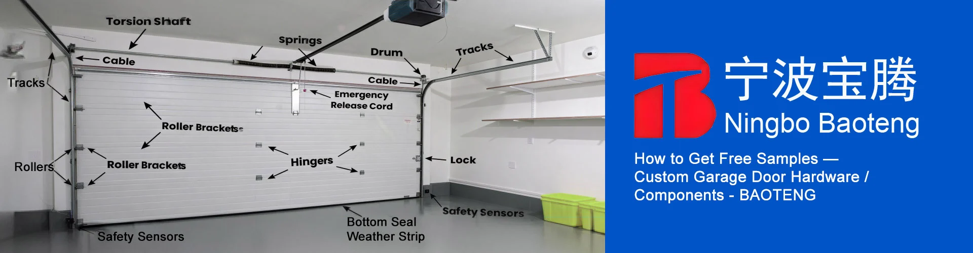
The most useful way to understand an industrial joint angle iron garage door track bracket geometry support role is to stop treating the bracket as a loose accessory. In a sectional or industrial door layout, the door panel moves, the track remains fixed, and the angle iron or bracket becomes the quiet reference point that keeps the support line from drifting. When the catalog lists 2.0mm, 2.3mm and 2.5mm, or 4.0mm steel thickness ranges, those values describe more than sheet size. They indicate where the part may sit in the structural conversation between alignment, stiffness, installation tolerance, and long-term service vibration.
The BT-A304 Industrial Joint Angle Iron sits at 2.0mm thickness with a galvanized finish. A 2.0mm bent steel part can serve as a practical connector where the geometry must remain defined but the part still needs to be workable during installation. In contrast, the BT-A310 Beam Support Bracket is listed at 4.0mm thickness, which places it in a stronger support conversation. The catalog does not state load capacity, so no numeric carrying force should be claimed. Still, from a mechanical viewpoint, a thicker steel bracket generally resists bending under the same installation disturbance better than a thinner sheet form, assuming comparable material and geometry.
The hidden challenge is the moment path. A door track does not only receive straight-line force. It experiences small repeated impulses from door movement, roller travel, vibration, fastener preload, and occasional alignment correction during service. A joint angle iron positioned between the track and support structure must resist not only direct pull but also small angular changes. When hole spacing, bend angle, or flatness is inconsistent, the installer may compensate by forcing the fastener path. That compensation can create a preloaded distortion before the door even moves.
A useful edge-case model is a humid warehouse door line with frequent opening cycles, fine dust, and temperature swings. In the early stage, a 2.0mm galvanized angle iron may look visually acceptable while minor misalignment shows only as extra effort during bolt insertion. In the middle stage, repeated micro-vibration can amplify a small angle error into a visible mismatch between the bracket face and track line. In the limit stage, the connection may not fail suddenly, but the system can show loosening, local rubbing, and uneven track support.
A cross-dimensional comparison helps clarify this. Compare a 2.0mm Industrial Joint Angle Iron used as a geometry connector with a 4.0mm Beam Support Bracket used as a support element. The first is more sensitive to hole accuracy and bend consistency because it often defines relative position. The second is more sensitive to support-plane stability because it is placed in a heavier structural conversation. Both require thickness confirmation, but they answer different installation questions.
When Bracket Thickness Changes the Installation Conversation Before Any Door Failure Appears
Thickness changes the buyer’s question before any visible defect appears. A buyer looking at 1.8mm and 2.0mm vertical or curve track parts may focus on track forming, length consistency, and roller-path continuity. A buyer reviewing a 2.0mm Industrial Joint Angle Iron may ask whether the bend angle and hole pattern match the intended fixing line. A buyer comparing 2.3mm and 2.5mm Joint Angle Iron may be trying to reduce the risk of installation flex. A buyer considering a 2.5mm Side Bracket with length options from 90mm to 150mm may be matching track position to a real installation envelope. A buyer checking a 4.0mm Beam Support Bracket is usually thinking about stronger support geometry, not just a simple replacement part.
The catalog gives a useful selection ladder:
| Component group | Catalog thickness or size data | Surface description | Main selection conversation |
|---|---|---|---|
| Vertical Track | 1.8mm and 2.0mm | Galvanized steel | Track path continuity and forming consistency |
| Curve Track | 1.8mm and 2.0mm | Galvanized steel | Curved movement transition and alignment |
| Industrial Joint Angle Iron | 2.0mm | Galvanized | Fixed connection geometry |
| Joint Angle Iron | 2.3mm and 2.5mm | Pre-galvanized or galvanized | Bend stiffness and hole-position repeatability |
| Side Bracket | 2.5mm, 90mm to 150mm length | Galvanized | Track fixing location and installation reach |
| Beam Support Bracket | 4.0mm | Galvanized | Support-plane stability |
This is not a ranking from weak to strong, because geometry, fixing method, hole pattern, and installation position matter. A 2.5mm part with poor bend accuracy can create more trouble than a 2.0mm part with stable geometry. The technical question is not simply “Which is thicker?” It is “Which thickness belongs to which function, and how does that function affect the track line?”
A practical extreme scenario is a replacement installation in a dusty service environment where the original fixing line is not perfectly square. During the initial stage, the installer notices that one hole starts easily while another resists. During the middle stage, tightening one fastener pulls the bracket face slightly out of plane. During the limit stage, track support may feel acceptable at rest but inconsistent during door travel. No catalog data supports a specific failure time, so the correct control method is not a time claim; it is dimensional verification before installation.
A cross-dimensional test case would compare a 2.5mm Side Bracket and a 2.3mm or 2.5mm Joint Angle Iron under the same mock assembly. The Side Bracket should be evaluated for reach, hole position, and track fixing face. The Joint Angle Iron should be evaluated for bend angle, flatness, and hole-to-edge relationship. The result is not a marketing claim. It is a selection map that helps buyers ask better questions before ordering.
From Straight Track to Cross Beam: A Reverse Map of Where Angle Brackets Lose Precision
A reverse map starts at the visible installation problem and works backward. The installer may first see a track that does not sit cleanly, but the cause may be upstream: a length mismatch in the Side Bracket, a bend inconsistency in the Joint Angle Iron, a hole pattern issue in the Industrial Joint Angle Iron, or a support-plane issue near the Cross Beam. That is why garage door track bracket reverse alignment map thinking is more useful than a simple product list.
The catalog group creates a chain: Vertical Track at 1.8mm and 2.0mm, Curve Track at 1.8mm and 2.0mm, Cross Beam at 2.0mm, Side Bracket at 2.5mm with multiple length options, and Joint Angle Iron from 2.0mm to 2.5mm depending on model. When this chain is assembled, every part must agree with the same physical line. If one bracket face is slightly twisted, the track may still be installed, but the fasteners begin carrying a correction load rather than only a fixing load.
The underlying mechanism is basic material behavior. Galvanized or pre-galvanized steel parts are still steel-based components. Steel offers useful stiffness in thin sections, but sheet metal geometry depends heavily on bending accuracy and hole placement. When a bracket is punched, bent, stacked, transported, and installed, its final usefulness is controlled by accumulated tolerances. A small dimensional deviation in one part may be harmless. The same deviation across multiple linked parts can become an alignment problem.
One extreme environment model involves a large industrial door opening used throughout a humid workday. In the initial period, airborne moisture and dust do not immediately damage a galvanized surface, but they can collect around contact points and fastener seats. In the middle period, vibration from repeated door movement can reveal which bracket face was not fully seated. In the limit period, a small out-of-plane condition may show as track noise, localized rubbing, or repeated loosening at the connection. The key insight is that the first symptom is often fit inconsistency, not visible fracture.
A comparison test case could place a 2.0mm Cross Beam, a 2.5mm Side Bracket, and a 2.0mm Industrial Joint Angle Iron into a trial fixture. The goal is not to overload the assembly. The goal is to check whether the parts agree geometrically before force is added. If the parts require manual twisting to line up, the buyer has found a hidden precision issue. If the parts sit naturally with consistent hole alignment and contact, the assembly has stronger fit confidence.
KEY TAKEAWAYS
- Fastener resistance during first alignment can appear before visible bracket deformation.
- Uneven face contact between bracket and track line may signal accumulated tolerance rather than installer error.
- Repeated loosening after initial tightening can indicate that the bracket is correcting geometry instead of only holding position.
How a Factory Should Translate Galvanized Bracket Data Into Buyer-Side Fit Confidence
Factory-side communication should translate catalog data into buyer-side fit confidence without exaggeration. For this product group, the strongest data points are thickness, length, surface finish, and part function. The factory should not need unsupported claims about life span, salt spray hours, or certified load capacity unless such data is actually tested and documented. The more reliable approach is to explain how catalog variables are controlled through practical inspection.
Solution 1: Thickness confirmation before forming and packing
Execution Protocol: Material should be checked against the catalog thickness category before it is treated as a finished bracket or track part. The inspection logic should separate 1.8mm and 2.0mm track parts, 2.0mm Industrial Joint Angle Iron, 2.3mm and 2.5mm Joint Angle Iron, 2.5mm Side Bracket, and 4.0mm Beam Support Bracket. This prevents a support part and a geometry connector from being evaluated under the same assumption.
Expected material evolution: Correct thickness grouping improves predictable stiffness during bending and fastening. It does not guarantee performance by itself, but it reduces the chance that a part behaves too flexibly for its intended installation role.
Hidden cost and control: Overchecking every piece may slow packing, while underchecking invites mixed batches. A reasonable control point is batch-level thickness sorting combined with targeted dimensional confirmation for critical brackets.
Solution 2: Hole position and bend-angle validation
Execution Protocol: Joint Angle Iron and Side Bracket parts should be reviewed for hole spacing, hole diameter consistency, bend angle, and flatness. For a track bracket, the holes are not decorative. They define how the fastener path meets the fixed support line.
Expected material evolution: Stable hole and bend geometry reduces forced installation. When the bracket sits without twist, fastener preload is more likely to clamp the intended surfaces instead of correcting shape error.
Hidden cost and control: Tight dimensional sorting can increase rejection if forming setup is unstable. The corrective action should focus on die condition, punch wear, and bend repeatability rather than simply discarding more parts.
Solution 3: Surface finish review for galvanized and pre-galvanized parts
Execution Protocol: Galvanized, pre-galvanized, and galvanized steel surfaces should be checked for missing coating, heavy scratches, white rust, burrs, and handling damage. The catalog identifies these surface systems, but surface wording alone does not confirm final condition.
Expected material evolution: An intact zinc-coated surface helps delay ordinary steel oxidation in humid oxygen-bearing environments. Damaged edges or deeply scratched zones can expose the steel substrate and create localized corrosion points.
Hidden cost and control: Too much handling after surface finishing can reduce visual quality. Packing separation and careful stacking reduce avoidable surface abrasion.
Solution 4: Trial-fit validation for track and beam relationships
Execution Protocol: Selected parts should be trial-fitted in a representative assembly relationship: Vertical Track, Curve Track, Cross Beam, Side Bracket, Beam Support Bracket, and Joint Angle Iron should be checked for natural alignment. The point is to verify compatibility of the geometry chain, not to create an unsupported performance claim.
Expected material evolution: A naturally seated assembly distributes clamping pressure more evenly and reduces the chance of stored installation stress.
Hidden cost and control: Trial fitting takes time, so it should focus on new batches, changed tooling, or mixed model orders.
| Inspection variable | Relevant catalog data | Expected fit behavior | Practical validation basis |
|---|---|---|---|
| Thickness category | 1.8mm to 4.0mm | Function-specific stiffness response | Material thickness check |
| Length category | 90mm to 150mm Side Bracket, 460mm and 530mm Flap-shaped Joint Angle Iron | Proper installation reach | Length verification |
| Surface system | Galvanized, pre-galvanized, galvanized steel | Resistance to ordinary surface oxidation when coating is intact | Visual surface review |
| Bend geometry | Angle iron and bracket forms | Stable face contact | Bend angle and flatness check |
| Track relationship | Vertical Track, Curve Track, Cross Beam | Continuous support path | Trial assembly review |
PRO-TIP / CHECKLIST
- Confirm whether the part is a track component, angle connector, side bracket, or beam support bracket.
- Match thickness to the catalog role before discussing installation behavior.
- Check length options carefully when selecting side brackets for track fixing.
- Review hole position before tightening fasteners in a real installation.
- Inspect galvanized or pre-galvanized surfaces for deep scratches, burrs, and exposed steel.
- Use a mock assembly when multiple track and bracket parts are ordered together.
- Avoid claiming load rating, service life, or corrosion-hour data unless a separate test report supports it.
For related product context and manufacturer information, review Baoteng industrial door hardware resources.
Frequently Asked Questions (FAQ)
How to reset garage door hardware alignment after bracket replacement?
Start by checking whether the track, side bracket, angle iron, and beam support line sit naturally before final tightening. Do not force all holes into position with fastener torque. If the bracket corrects geometry by twisting, the track may look installed but remain under hidden stress.
How to program your garage door opener after track bracket work?
Programming the opener is separate from bracket alignment. Before programming, confirm the door moves smoothly by hand and the track line is not binding. A motorized opener should not be used to overcome mechanical resistance from misaligned brackets or tracks.
Where can I buy a garage door opener if the bracket system is also worn?
Buy the opener only after confirming the door hardware is mechanically sound. If track brackets, angle irons, or support brackets show alignment problems, replacing the opener will not solve the mechanical issue. Hardware fit should be checked before electrical drive selection.
What thickness is used for Industrial Joint Angle Iron in the catalog?
The catalog lists BT-A304 Industrial Joint Angle Iron with 2.0mm thickness and a galvanized finish. Related joint angle iron models include 2.0mm, 2.3mm, and 2.5mm options, depending on model and finish type.
What makes a garage door track bracket difficult to install?
Common causes include hole-position deviation, bend-angle inconsistency, length mismatch, face flatness issues, and surface damage around punched or bent zones. The first visible symptom is often bolt alignment difficulty rather than complete bracket failure.
 English
  Русский
  日本語
日本語  한국어
한국어  Français
  Deutsch
  العربية
  Português
  Español