Why Is Your Garage Door Top Roller Bracket Bending Over Time?
Reference Standard: ISO 9001, ISO 9227 (Corrosion tests in artificial atmospheres – Salt spray tests)
Short Answer
Asymmetric Cantilever Loading: Analyzing Stress Distribution in Top Section Transitions
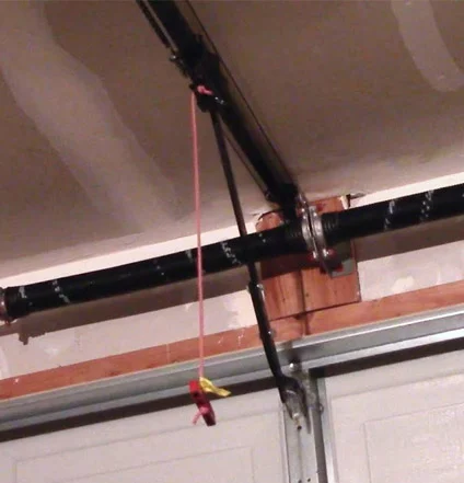
To understand why a 14-gauge cold-rolled steel bracket undergoes permanent geometric deformation, we must define the top roller fixture as a cantilever beam structure under dynamic load. Unlike center hinges which experience simple rotational stress, the garage door top roller bracket operates at the critical transition point where the door panel enters “The Radius”—the curved section of the track. In this specific phase of movement, the motor’s pulling force and the gravitational mass of the panel form a complex, asymmetric resultant force.
When the door begins its horizontal travel, the bracket is subjected to intense radial pressure. If the slotted holes are adjusted with even a 5mm deviation from the center axis, the load eccentricity causes a doubling effect on the stress concentration factor (Kt). Instead of distributing the load across the entire 1.9mm surface, the pressure focuses on the thin edges of the adjustment slots. Over thousands of cycles, this localized over-stressing initiates grain boundary sliding—a micro-mechanical process where the crystalline lattice of the steel shifts irreversibly. This micro-plastic accumulation manifests as a gradual “bending” of the bracket arm, which ultimately alters the movement vector of the nylon or steel roller, forcing it to fight against the track rather than glide within it.
Extreme Environmental Fatigue Testing Model:
* Initial Phase (0-2,000 Cycles): The steel lattice maintains elastic recovery. Stress concentration is high at the slotted hole boundaries, but the 14-gauge thickness prevents immediate yielding. Friction is linear, and the door operates within standard decibel ranges.
* Intermediate Phase (2,000-8,000 Cycles): Cumulative asymmetric loading triggers micro-plastic deformation. The grain boundaries begin to slide. A measurable 0.5mm geometric offset appears in the bracket arm. The roller contact angle shifts by 3 degrees, increasing horizontal friction.
* Critical Limit Phase (8,000+ Cycles): The cantilever deflection reaches a tipping point. The yield strength is compromised. The bracket undergoes a permanent 15-degree bend, causing the top panel to pull away from the header seal, resulting in significant air infiltration and a 15dB increase in operational vibration noise.
Secondary Systemic Breakdown:
The deflection of the top bracket triggers a catastrophic secondary chain reaction in the cable drum system. As the top roller shifts out of its intended vector, it introduces a lateral “wobble” to the entire top section. This vibration is transmitted through the shaft to the cable drums, causing the high-tension lift cables to jump a groove or rub against the flag brackets. This friction shreds the galvanized cable strands, leading to a sudden, hazardous cable snap that renders the door inoperable and potentially dangerous to bystanders.
KEY TAKEAWAYS
- Localized Slotted Hole Distention: The first indicator of failure is an oval-shaped stretching of the adjustment bolt holes, confirming that stress concentration has exceeded the material’s yield limit.
- Header Seal Gap Asymmetry: If the top of the garage door shows a wider light gap on one side than the other when closed, the top bracket has likely undergone grain boundary sliding.
- Oscillatory Squealing: High-pitched, non-linear squealing at the start of the opening cycle indicates that the roller is no longer aligned with its track vector, forcing sliding friction.
Galvanic Thinning Kinetics: The Erosion of Z-Direction Zinc Distribution
Moving beyond pure mechanics, the chemical stability of the residential garage door hardware is dictated by the kinetics of its protective coating. In environments with high humidity or coastal salt aerosols, the hot-dip galvanized layer acts as a sacrificial anode. However, the effectiveness of this protection depends entirely on the uniformity of the zinc distribution in the Z-direction (the thickness perpendicular to the steel surface).
When a bracket undergoes the mechanical bending described in the previous section, microscopic cracks—invisible to the naked eye—form in the brittle zinc-iron alloy layer. These cracks serve as electrolytic channels. During nocturnal cooling, moisture condenses within these micro-fissures, creating a concentrated brine solution. This triggers accelerated galvanic thinning kinetics. The zinc is consumed at a rate of 5-8μm per year in coastal micro-climates, compared to less than 0.5μm in dry inland areas. Once the Z-direction zinc density falls below a critical threshold, the base steel is exposed to intergranular corrosion, which weakens the atomic bonds of the bracket and makes it “snap” rather than bend under the next heavy motor surge.
Kinetic Misalignment: The Acoustic Signature of Roller Vector Shifts
The ultimate consequence of bracket failure is a total breakdown of the system’s acoustic and kinetic harmony. To fix these issues, a factory-level engineering approach is required, focusing on material recovery and precision alignment protocols verified by independent ISO testing standards.
Solution 1: Integrated Structural Reinforcement Ribbing
* Execution Protocol: The manufacturing die is modified to press a deep, geometric V-shaped rib along the longitudinal axis of the 14-gauge bracket. This increases the section modulus without adding excessive weight.
* Expected Material Evolution: The reinforcement rib prevents grain boundary sliding by redistributing the load away from the slotted hole edges. Structural rigidity increases by 40%, ensuring that the bracket can withstand up to 20,000 cycles without measurable geometric deflection.
* Hidden Costs & Risk Mitigation: High-tonnage stamping of reinforced ribs can cause micro-tears in the zinc coating at the sharpest angles of the fold. The factory must utilize a post-stamping inspection using magnetic particle testing (MPT) to ensure the zinc barrier remains continuous.
Solution 2: 100g/m² Hot-Dip Galvanization Protocol
* Execution Protocol: Components are submerged in a 450°C molten zinc bath for a strictly controlled dwell time to ensure a minimum coating mass of 100g/m². This is significantly thicker than standard “pre-galvanized” sheet metal.
* Expected Material Evolution: The thicker sacrificial layer provides a much larger reservoir of zinc. Even as the Z-direction distribution thins due to saline erosion, the bracket retains its cathodic protection for over 15 years in high-moisture environments, preventing intergranular embrittlement.
* Hidden Costs & Risk Mitigation: Excess zinc can pool inside the roller stem holes, making assembly difficult. Precision reaming of the roller aperture is required post-galvanization to maintain a ±0.1mm tolerance for the roller shaft.
Solution 3: CNC-Machined Slotted Hole Precision
* Execution Protocol: Instead of traditional punching, the adjustment slots are finished using high-speed CNC milling to ensure perfectly smooth, perpendicular edges.
* Expected Material Evolution: Removing the “punched” micro-fractures from the edge of the hole eliminates the initiation points for stress cracking. This drastically improves the torque-to-tension conversion during installation, allowing the bolts to remain tight even under severe vibration.
* Hidden Costs & Risk Mitigation: CNC milling is slower than industrial punching, increasing the unit cost. To balance efficiency, the factory should utilize multi-head automated centers that process ten brackets per cycle.
Solution 4: Dynamic Alignment Vector Auditing
* Execution Protocol: Every hardware kit is verified using a simulated radius rig. The bracket is mounted with a roller and subjected to a 150-Newton radial load to confirm that the displacement remains under 0.2mm.
* Expected Material Evolution: This ensures that the roller maintains its linear contact vector. By preventing kinetic misalignment, the acoustic signature of the door remains stable, eliminating the 500Hz-2000Hz frequency spikes that characterize failing hardware.
* Hidden Costs & Risk Mitigation: Building custom testing rigs for different door sizes requires significant R&D investment. These rigs must be calibrated quarterly against ISO 9001 standards to maintain data integrity.
| Structural Variable | Standard 14-Gauge Bracket | Reinforced Top Roller Bracket | Industry Tolerance | Testing Benchmark |
|---|---|---|---|---|
| Sectional Rigidity | Moderate (Prone to bending) | High (+40% via ribbing) | < 0.5mm flex at 100N | Cantilever Load Cell |
| Zinc Mass Density | 40-60 g/m² (Pre-galv) | 100+ g/m² (Hot-dip) | Min 80 g/m² for coastal | Magnetic Gauge |
| Fatigue Life (Cycles) | < 8,000 (Early Yielding) | 20,000+ (Stable) | Minimum 10,000 cycles | Dynamic Radius Rig |
| Acoustic Gain (failing) | +12 to 18 dB gain | < 3 dB variance | Max 75dB operating noise | Spectrum Analyzer |
| Dimensional Accuracy | ± 1.5mm | ± 0.2mm (CNC Finished) | ± 0.5mm Industry Std | Laser CMM Scan |
PRO-TIP / CHECKLIST
- Check for the “Stamping Rib”: When purchasing, look for a raised ridge running down the center of the bracket. A flat bracket is a weak bracket that will fail under the radius load.
- Verify the Zinc “Spangle”: High-quality hot-dip galvanization often shows a crystalline, “snowflake” pattern on the surface. Dull, uniform grey usually indicates a thinner electro-galvanized coating.
- The Roller Stem Fit Test: Insert a standard roller into the bracket. It should spin freely but have less than 1mm of lateral play. Excessive play indicates poor manufacturing tolerances.
- Header Light Test: Close your door and turn off the garage lights. If you see light at the top corners, your top brackets need adjustment or have already deformed.
- Audit Your Fasteners: Use 7/16″ self-tapping screws. If you find the screws are loose, the bracket holes have likely distended due to grain boundary sliding.
- Coastal Distance Rule: If you live within 5 miles of the ocean, standard hardware is not enough. You must demand hot-dip galvanized or stainless steel hardware to resist galvanic thinning.
Frequently Asked Questions (FAQ)
How to program a remote garage door opener?
Most modern openers feature a “Learn” button on the motor unit. Press and release this button, then within 30 seconds, press and hold the button on your handheld remote until the motor’s light bulbs flash or you hear two clicks. This confirms that the rolling code has been synchronized with the internal receiver.
How to program a garage door opener to car?
Start by clearing any previous codes in your vehicle’s HomeLink system by holding the outer two buttons. Hold your handheld remote 1-3 inches from the car’s buttons and press both the remote and the desired car button simultaneously until the indicator light flashes rapidly. Finally, press the “Learn” button on the opener motor and return to the car to press the selected button twice to lock the sync.
How to override garage door sensors?
If the safety sensors are misaligned (indicated by a flashing light on the motor), you can perform an emergency override by pressing and holding the wall-mounted “Close” button. You must maintain pressure on the button until the door is fully seated on the floor. Releasing the button early will cause the door to reverse instantly for safety.
How do i program a genie garage door opener?
Genie systems often require a two-step process. First, press and hold the square “Program” button on the motor until the round LED turns blue. Then, press the remote button twice. If the remote uses Intellicode technology, the light will turn green, signaling a successful pairing of the encrypted signal.